IMHO passive I/V for the TDA1543 doesn't have the dynamics which are obtainable with an active stage.
I also noticed passive I/V is very sensitive to the load (preamp and cables).
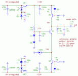
Finally finshed some boards and put them in.
The I/V is similar to the one here:
http://www.diyaudio.com/forums/showthread.php?s=&threadid=9226&highlight=simple+TDA1541
TDA1543 is still powered by 8V, bias pot has been removed from pin 7. Will try later with 6.1V and 5V.
NOTE: R6 is multiturn pot to set the Vc(Q3) DC level, I choose 10V
As I hoped, dynamics improved a lot compared to passive I/V.
It's got firm tight bass and sounds very transparent.
Compared to the TDA1541A-S1 with similar I/V this comes really close. The TDA1541A-S1 has more micro-detail, more texture to voices and instruments, but the TDA1543 sounds (surprisingly) more transparent and bass control is a bit tighter.
In fact my girlfriend prefers the TDA1543 now, thinks it's less irritating than the TDA1541A-S1 when the volume is up.
Application: Philips CD player, non-oversampling, Kwak-Clock similar to version 6/7, synchronous BCK reclocking with VHC logic, output caps are Audyn KpSn (Tin-Foil)
If somebody tries he/she could experiment to find the (soundwise) optimal voltage for the DAC's output, by changing the base voltage on Q3.
Enjoy,
Attachments
Rudolf,
I have a question. Since the DAC would ideally like to see 0 VDC at its output to minimize distortion, why not replace D3, D4 by a single diode-connected transistor. That will get the input offset very close to zero, especially if you give it the same current.
Jan Didden
I have a question. Since the DAC would ideally like to see 0 VDC at its output to minimize distortion, why not replace D3, D4 by a single diode-connected transistor. That will get the input offset very close to zero, especially if you give it the same current.
Jan Didden
Simple Active IV for TDA1543
Hi Rudolf,
This is certainly something I am going to try too!
The difference in current supplied by the current source Q1 and the current sink Q4, is to compensate for the static current from the DAC?
What did you connect to Vref ?
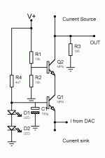
I would also try a second common base connected transistor for Q3. (Fig. 12-9 page 235 in Low-Noise Electronic Design by Motchenbacher and Fischer.) "The CB-CB pair is useful as a wideband current amplifier."
Janneman,
See the link for the TDA1541 I/V.
But now, this DAC's voltage compliance is NOT 0V, but 1.8V to Vdd-1.2V
That's why any voltage within that band will do.
Elso,
The Current source supplies the total of the current sink, DAC bias current and DC current through Riv to get some Vce(Q3).
I think pot R6 is like 60~80 ohms or so.
I must admit, the Vce(Q3) is a bit low. But the results are still very good.
I left Vref unconnected.
One might experiment connecting a capacitor to it to find out if there are audible differences.
My next I/V version will indeed have a cascode. I carefully noticed Jocko's hints. It will be a folded cascode with another current sink that's cascoded by a J111 fet. This one shall be DC coupled !
Then I will start using some better BJT's like 2SA1085E & 2SC2547E
Cheers,
rbroer said:
I left Vref unconnected.
One might experiment connecting a capacitor to it to find out if there are audible differences.
Seems risky to me. The input could be susceptible for noise now. And I think that a proper DC level helps for minimising the distortion level of the DAC. Just try attaching a pot...
Fedde
rbroer said:Janneman,
See the link for the TDA1541 I/V.
But now, this DAC's voltage compliance is NOT 0V, but 1.8V to Vdd-1.2V
That's why any voltage within that band will do.
[snip]Cheers,
OK Rudolf, I didn't look at the link, that is indeed what I meant. But, beg pardon, in your latest diagram the input offset is shown as 2.4V, which is outside the 1.8 to -1.2 you quoted (which I have not verified, too lazy I'm afraid). Then again, although a compliance spec is given for operation within a (reasonable) linear range), ALL DACs I have seen work optimal with a zero offset into a zero impedance. Your call of course, just wondering why the change.
Jan Didden
Ok Jan,
one more try before I give up:
TDA1543 voltage compliance is 1.8V to Vdd-1.2V
With a Vdd of 8V the voltage compliance is 1.8V ~ 6.8V

So anywhere between will do.
This is why the TDA1543 is quite special and one can almost have 2Vrms output swing PASSIVE,
by carefully selecting Vdd, Rbias and Riv
I think Fred called this DAC a:
hybrid transconductance device with voltage feedback (about 2k open loop output Z,so not a true current out device)

one more try before I give up:
TDA1543 voltage compliance is 1.8V to Vdd-1.2V
With a Vdd of 8V the voltage compliance is 1.8V ~ 6.8V

So anywhere between will do.
This is why the TDA1543 is quite special and one can almost have 2Vrms output swing PASSIVE,
by carefully selecting Vdd, Rbias and Riv
I think Fred called this DAC a:
hybrid transconductance device with voltage feedback (about 2k open loop output Z,so not a true current out device)
rbroer said:Ok Jan,
one more try before I give up:
TDA1543 voltage compliance is 1.8V to Vdd-1.2V
With a Vdd of 8V the voltage compliance is 1.8V ~ 6.8V

So anywhere between will do.
This is why the TDA1543 is quite special and one can almost have 2Vrms output swing PASSIVE,
by carefully selecting Vdd, Rbias and Riv
I think Fred called this DAC a:
hybrid transconductance device with voltage feedback (about 2k open loop output Z,so not a true current out device)

OK yes, I mixed up those voltage levels. Seems you know what you're doing, still don't see why. But that's OK.
Jan Didden
Just my small contribution to the discussions in this posting tail
current source output: The Output impedance is aprox 40kOhm (not the 2kOhm mentioned here). I just measured it to make sure we do have a real current source on hand. With a Rload in the range of a few kOhm (2k2 delivers 1,6 Volt RMS at 0dB) this is a relatively save statement. 2k7 would do exactly the 2VRMS CD standard by the way....
The distortion of a 0dB 1kHz sinewave, stays below 60dB for d2 and d3 when a proper DC adjustment is done. I have used 1350 Ohm for the Rref and 2k2 for the Rload. The VCC is 8,5 Volt. This delivered the best results, with trimming with help of a FFT analyzer, as well listening tests. But do not worry too much, as long as the DC component of the Output is between 3,7 and 4,1 Volt (with a VCC between 7,5 and 8,5Volt) the results are relatively similar. Outside this bandwidth the d2 and d3 increase very rapidly with a factor 10-30!! Very easy to hear as well, as human voices loose the smooth clean character. This will happen already below 3.5 Volt DC and above 4,4 Volt. When the VCC drops below 7.5, bass becomes thin and dynamics are less.
Actually a lot of problems described here can be omitted if a amplifierstage is used with a high Ri, like a tube stage or a Volume pot of more than 100kOhm (also nice to have low Cap in the interlink with all my experiments and testings (also with other DAC's with current outputs) this normally is the cause, as well the use of relatively "poor" signal caps after the DAC ( !! )
Oh, by the way, 3 DAC's in parallel, beats easily one DAC. Much more soundstage, and microdetail..... just put 3 pieces on top of each other and reduce the Rref and Rload by 3.....
Have 1543 fun !
Doede
current source output: The Output impedance is aprox 40kOhm (not the 2kOhm mentioned here). I just measured it to make sure we do have a real current source on hand. With a Rload in the range of a few kOhm (2k2 delivers 1,6 Volt RMS at 0dB) this is a relatively save statement. 2k7 would do exactly the 2VRMS CD standard by the way....
The distortion of a 0dB 1kHz sinewave, stays below 60dB for d2 and d3 when a proper DC adjustment is done. I have used 1350 Ohm for the Rref and 2k2 for the Rload. The VCC is 8,5 Volt. This delivered the best results, with trimming with help of a FFT analyzer, as well listening tests. But do not worry too much, as long as the DC component of the Output is between 3,7 and 4,1 Volt (with a VCC between 7,5 and 8,5Volt) the results are relatively similar. Outside this bandwidth the d2 and d3 increase very rapidly with a factor 10-30!! Very easy to hear as well, as human voices loose the smooth clean character. This will happen already below 3.5 Volt DC and above 4,4 Volt. When the VCC drops below 7.5, bass becomes thin and dynamics are less.
Actually a lot of problems described here can be omitted if a amplifierstage is used with a high Ri, like a tube stage or a Volume pot of more than 100kOhm (also nice to have low Cap in the interlink
Oh, by the way, 3 DAC's in parallel, beats easily one DAC. Much more soundstage, and microdetail..... just put 3 pieces on top of each other and reduce the Rref and Rload by 3.....
Have 1543 fun !
Doede
CB-CB Pair
Hi Rudolf,
Here it is. I omitted to draw the voltage regulators and the current source and sink only designated with text. A cap could also be added at the base of Q2 with is simply set to half the supply voltage with a voltage divider.
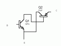
Jan I wondered why you did not bring up the Sziklai connection as published by you in The Audio Amateur 2, 1989?
(next picture)
Attachments
Hi Doede, nide to see you on the forum.
Well, this is my 3rd TDA1543 experiment.
In fact, a few years ago, I started with 3 parallel TDA1543 at ca. 8V and with adjusted Rref and Riv
Later implemented a single TDA1543 at 8V with passive I/V which I prefered over the parallel...
But with the active I/V it really gets punch IMHO.
The 4V DC level for passive I/V complies with the info in the datasheet:
DAC output compliance is 1.8V to Vdd-1.2V, so with Vdd=7.5V the output swing is 1.8V to 6.3V maximum. So the DC level should be right in the middle, in this case 4.05V (according to the numbers in the datasheet).
With a scope and a multiturn pot for the bias current one can finetune that DC voltage level, by finding the exact clipping voltages and adjusting the dc level right in the middle.
With the active I/V, the voltage on the DAC's output will be the held constant by the common base.
Anywhere between 1.8V to Vdd-1.2V is ok. Since we don't know the exact internal output circuits of the TDA1543, it's hard to tell if there is an optimal setting...Same for the supply voltage, since one doesn't need the 8V anymore.
I remember Elso mentioning 5V sounding less metalic than 8V, using his active I/V circuit.
BTW Doede,
Would you be interested in "grading" these TDA1543's
I know Reichelt sells them for less than a Euro each,
you could get a bunch and sort them on -60dB singal THD level.
The best ones could be stamped with a CROWN and sold to the inmates for a nice price (covering your expenses of course).
Just an idea
Well, this is my 3rd TDA1543 experiment.
In fact, a few years ago, I started with 3 parallel TDA1543 at ca. 8V and with adjusted Rref and Riv

Later implemented a single TDA1543 at 8V with passive I/V which I prefered over the parallel...

But with the active I/V it really gets punch IMHO.
The 4V DC level for passive I/V complies with the info in the datasheet:
DAC output compliance is 1.8V to Vdd-1.2V, so with Vdd=7.5V the output swing is 1.8V to 6.3V maximum. So the DC level should be right in the middle, in this case 4.05V (according to the numbers in the datasheet).
With a scope and a multiturn pot for the bias current one can finetune that DC voltage level, by finding the exact clipping voltages and adjusting the dc level right in the middle.
With the active I/V, the voltage on the DAC's output will be the held constant by the common base.
Anywhere between 1.8V to Vdd-1.2V is ok. Since we don't know the exact internal output circuits of the TDA1543, it's hard to tell if there is an optimal setting...Same for the supply voltage, since one doesn't need the 8V anymore.
I remember Elso mentioning 5V sounding less metalic than 8V, using his active I/V circuit.
BTW Doede,
Would you be interested in "grading" these TDA1543's

I know Reichelt sells them for less than a Euro each,
you could get a bunch and sort them on -60dB singal THD level.
The best ones could be stamped with a CROWN
 and sold to the inmates for a nice price (covering your expenses of course).
Just an idea
Further thoughts on "active IV"
Hi Rudolf,
On further thought it might be an idea to combine the Sziklai and the second CB transistor, using three transistors in total. Also a LH0003 style or Walt Jung outputbuffer might be added and the second transistor folded. Or cascode the current sources.....And make the whole circuit complementary to avoid offset....
Actually I believe the IV-conversion is still passive using the current flowing through the resistor...
But I don't know how the similation sounds!
Welcome a-board Doede 
Thanks for sharing the output impedance information. Combined with the mentioned 47 Labs output impedance (2.3 k), this means they must be using 2.4 k I/V resistors and a single DAC. Now I only wonder what supply and reference they use. Well, the I/V was the most important parameter! The supply is still a mystery for me, as I heard that the Progression and Shigaraki are fed with 5.56 V supplies. In the Stereophile article they talk about 12 V DC supplies (http://www.stereophile.com/printarchives.cgi?800). That seems more logical.
I have two non-os (and Nonoz) DACs now, one at 8V with 2.2 k I/V and one at 6V with 1k I/V. I prefer the 8V version now. Why? It sounds more sexy
Fedde
Thanks for sharing the output impedance information. Combined with the mentioned 47 Labs output impedance (2.3 k), this means they must be using 2.4 k I/V resistors and a single DAC. Now I only wonder what supply and reference they use. Well, the I/V was the most important parameter! The supply is still a mystery for me, as I heard that the Progression and Shigaraki are fed with 5.56 V supplies. In the Stereophile article they talk about 12 V DC supplies (http://www.stereophile.com/printarchives.cgi?800). That seems more logical.
I have two non-os (and Nonoz) DACs now, one at 8V with 2.2 k I/V and one at 6V with 1k I/V. I prefer the 8V version now. Why? It sounds more sexy

Fedde
Elso, Pierre-Frédéric Caillaud (peufeu) made something similar about year ago using J309. He said he will publish his own work… still nothing… but I had once information from him, he said this folded cascade do sounds better. Pierre, are you lurking? (And I agree with you, all this still can be called a passive conversion, though the DAC’s out is buffered.)
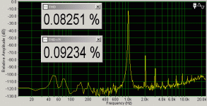
Doede, can you post your distortion measurements? Scott Nixon once claimed 20% distortion with the configuration you mentioned, 60dB looks far better, sounds a bit too good to be true... I attached the measurement done using 6V supply and 1k I/V resistors (chip is plain vanilla, i.e. not crowned TDA1543 ).
).
Rudolf, sorry for hijacking the thread… hmm, can you make some measurements?
Pedja
Doede, can you post your distortion measurements? Scott Nixon once claimed 20% distortion with the configuration you mentioned, 60dB looks far better, sounds a bit too good to be true... I attached the measurement done using 6V supply and 1k I/V resistors (chip is plain vanilla, i.e. not crowned TDA1543
Rudolf, sorry for hijacking the thread… hmm, can you make some measurements?
Pedja
Attachments
Hi Pedja,Pedja said:Elso, this is something like that what Pierre-Frédéric Caillaud (peufeu) made about year ago using J309. He said he will publish his own work… still nothing… but I had once information from him, he said this folded cascade do sounds better. Pierre, are you lurking? (And I agree with you, all this still can be called a passive conversion, though the DAC’s out is buffered.)
Doede, can you post your distortion measurements? Scott Nixon once claimed 20% distortion with the configuration you mentioned, 60dB looks far better, sounds a bit too good to be true... These measurements are done using 6V supply and 1k I/V resistors (chip is plain vanilla, i.e. not crowned TDA1543).
Rudolf, sorry for hijacking the thread… hmm, can you make some measurements?
Pedja
Sorry I do not follow reasoning. By "this" you mean the Sziklai connection?. Cascoding current sources I did long before Peu Feus posting on AA. You mean folded cascode??
In fact a CB-CB pair isn' t a cascode; that would be a CE-CB pair.
- Status
- This old topic is closed. If you want to reopen this topic, contact a moderator using the "Report Post" button.
- Home
- Source & Line
- Digital Source
- Simple ACTIVE I/V for TDA1543


