Thanks all for your input.
Very much thanks 'dvv' for your valuable info and feedback. I have learned a lot here. As i said earlier that this '980W' amp was only an idea and I am not gonna build this. Not now at least.
"First, how much power do you want under which circustances?"
Firstly, my speakers are rated at 400W@4R(a 12" pioneer 400W 2ohmDVC sub and a 50W 4" tweeter), so, I need a 250-300W@4R amp. I am gonna use it mostly at home with moderate listening levels. I listen to all kinds of music, but I am kind of Bass-head, so sometimes volume is cranked high. Also, it would be occasionally used for partying in a medium sized hall.
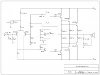
Secondly, I am currently using my old faithful 130W amp(schematic attached, also pics earlier in the thread) and I dont want to modify/tweak this amp, I am happy with it as it is. It has been used continuously for 5-6 hrs several times at max. power and it sounds nice and has proved reliable. So its often pushed hard , but this amp is underpowered for my speakers. Attached are links for the videos of my speakers banging with this amp.
https://www.youtube.com/watch?v=5FbB_5mK7ho
https://www.youtube.com/watch?v=YH33XBbSPWw
Thirdly,
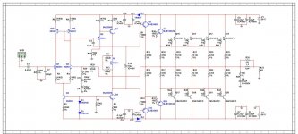
I need to build a new amp and expect 250-300W@4. So I am working on and tweaking this amp in the thread:, http://www.diyaudio.com/forums/solid-state/228463-anybody-know-amp.html
I already have its PCB and almost all parts and it worked well . With rails increased to +/- 60-63 volts and 4-5 pairs of outputs and TEF design we could achieve the power required. I am working on it and would post pics soon. Any advice is most welcome.
Thanks and Regards,")
Aniket
Very much thanks 'dvv' for your valuable info and feedback. I have learned a lot here. As i said earlier that this '980W' amp was only an idea and I am not gonna build this. Not now at least.
"First, how much power do you want under which circustances?"
Firstly, my speakers are rated at 400W@4R(a 12" pioneer 400W 2ohmDVC sub and a 50W 4" tweeter), so, I need a 250-300W@4R amp. I am gonna use it mostly at home with moderate listening levels. I listen to all kinds of music, but I am kind of Bass-head, so sometimes volume is cranked high. Also, it would be occasionally used for partying in a medium sized hall.
Secondly, I am currently using my old faithful 130W amp(schematic attached, also pics earlier in the thread) and I dont want to modify/tweak this amp, I am happy with it as it is. It has been used continuously for 5-6 hrs several times at max. power and it sounds nice and has proved reliable. So its often pushed hard , but this amp is underpowered for my speakers. Attached are links for the videos of my speakers banging with this amp.
https://www.youtube.com/watch?v=5FbB_5mK7ho
https://www.youtube.com/watch?v=YH33XBbSPWw
Thirdly,
I need to build a new amp and expect 250-300W@4. So I am working on and tweaking this amp in the thread:, http://www.diyaudio.com/forums/solid-state/228463-anybody-know-amp.html
I already have its PCB and almost all parts and it worked well . With rails increased to +/- 60-63 volts and 4-5 pairs of outputs and TEF design we could achieve the power required. I am working on it and would post pics soon. Any advice is most welcome.
Thanks and Regards,
Aniket
Attachments
Last edited:
Not at all, Aniket, you remind me of myself in my eraly days, which were the late 70ies. You are progressing faster than I did in those days, but then, we didn't have the Internet in those days.
Regarding your speakers, while power handling figures appear to be very high, the key spec is how efficient they are. If they are very efficient, you need less power, and vice versa, if they are inefficient, you need more power. There is no generally accepted levels for either, but I suppose you could say that if they can do 92 dB/2.83V/1m, that would be the low threshold of efficiency. If it does just 3 dB less efficiency wise, you would need double the power for the same SPL.
Please note I used VOLTAGES, not watts, as this takes the conversion from 8 to 4 Ohms out of the equation. Easier to talk.
Regarding the schematics you have posted, they are all well known designs, but from like 35 years ago. Trust me on this, we have come a long way since then, much has been learnt and done, partly due to the research of many a good man, and partly due to the fact that semiconductors have become dirt cheap in comparison with 35 years ago. Quite simply, we can use a lot more of them without feeling the price crunch, and it was this that redifined the minimum approach.
Rather than have me extoll virtues of modern design, I strongly recommend you obtain a copy of Bob Cordell's book. It's an ABC guide to designing amplifiers, with detailed and clear explanations and, in many cases, with all the required maths and procedures for this or that.
BTW, "dvv" are my real life initials, I am Dejan V. Veselinović, but I've been "dvv" since the late 80ies and the first BBS boards. I'm two months short of being 60, married, son 27 years old, graduated economics. I live in Belgrade, which is the capital of the Repiblic of Serbia, Balkan penninsula, Southern Europe. I am self-employed.
Last edited by a moderator:
Dear Sir Dejan, thanks a lot for all your support. I am a computer engg. aged 24 with a keen interest in audio electronics since childhood.
My speakers are rated at 91dB/2.83V/1m. freq response 20-220Hz for woofer and 500Hz-25kHz for tweeter-95dB sensitivity. 3.5 cu. feet ported enclosure tuned at 37Hz.
As for the book, i have both Bob Cordell and Douglas Self e-books in Pdf.
You are right Sir, i would read and understand these books thoroughly before going to hardcore designs. I have even started reading Bob Cordell's.
Thanks again for that.
Regards,
Aniket
"o.1 Ohm 5W 1% emitter resistors? Never seen anything like that. "
Digi-Key has 8 surface mount:
WSH2818R1000FEA Vishay Dale | WSHA-.1DKR-ND | DigiKey
And 50 through-hole.
ALSR05R1000FE12 Vishay Dale | ALSR5F-.10-ND | DigiKey
And 12 in 0.5%, and even a 0.1% model.
If you want 5%, they only have 25 (vs 50 in 1%).
Digi-Key has 8 surface mount:
WSH2818R1000FEA Vishay Dale | WSHA-.1DKR-ND | DigiKey
And 50 through-hole.
ALSR05R1000FE12 Vishay Dale | ALSR5F-.10-ND | DigiKey
And 12 in 0.5%, and even a 0.1% model.
If you want 5%, they only have 25 (vs 50 in 1%).
Last edited:
@djk
Many thanks for the useful links supplied.
I have a slight preference for fully complementary designs, and these rely heavily on low tolerances overall to work well. The matching of transistors is the obvious thing, but the rest also needs close tolerance.
I have honestly never seen high power resistors of close tolerance, i.e. 1%, always 5% best offer, most 10% (I refer to 5W and above resistors). But then, I didn't exactly kill myself looking for them, either.
Dear Sir Dejan, thanks a lot for all your support. I am a computer engg. aged 24 with a keen interest in audio electronics since childhood.
My speakers are rated at 91dB/2.83V/1m. freq response 20-220Hz for woofer and 500Hz-25kHz for tweeter-95dB sensitivity. 3.5 cu. feet ported enclosure tuned at 37Hz.
As for the book, i have both Bob Cordell and Douglas Self e-books in Pdf.
You are right Sir, i would read and understand these books thoroughly before going to hardcore designs. I have even started reading Bob Cordell's.
Thanks again for that.
Regards,
Aniket
Please Aniket, no "Sir" or anything, just dvv is fine.
You being a computer eng. is a bonus which will only help you.
Different sensitivities for woofer and tweeter are quite common, some of the tweeter's advantage in efficiency will be lost on the crossover and the rest of the difference should be ironed out by the crossover designers to give you a nominally level playing field.
So, let's assume that the nominal sensitivity of the loudspeaker system is 91 dB/2.83V/1m. So, roughly speaking, 400W/8 Ohms equals to 26 dBW, which would nominally let you achieve (91+26) 117 dB at 1m. This is a rough approximation only, other factors have been left out and disregarded. Again roughly, this is equivalent to a jet engine working at full blast at some 5 meters or so, in other words - deafening.
Long before you reach such levels, the window panes in your room will be rattling, and the neighbors will have called the cops.
I read somewhere that under normal home listening conditions, most of us spend 98% of our listening time using less than 1 Watt on a continuous basis, but some peaks (e.g. tympani, Japanese taiko drummers, symphonic orchestras, etc) will require much more power only to be reproduced in equal volume with the rest. 10 to 20 Watts is easily achieved with high quality recordings.
This neatly explains how tube buffs get away with 10-15W of power, and how so many commeercial products get away with relatively small heat sinks relative to their nominal power.
To cut a long story short, I would suggest that you go for a decent 100/200W into 8/4 Ohms, with say 1.5 or 2 dB dynamic headroom. In return, let it work in pure class A longer than usual, meaning make the bias (quiescent) current not the usual 30-50 mA, but say 110-130 mA. My experience is that you got what was there to get by around 130 mA, nothing left to be gained above that, except for going all pure class A.
Use 4 pairs of output devices, Toshiba's 2SC5200/2SA1943 are a good choice, Motorola/ON Semi's MJL 3281/1302 an even better one. I have tried the "4" versions, the ones with the integrated diode, and frankly, I was not pleased with what I got (I have been using Motorola power devices since the mid 70ies). The problem is finding the real deal, not fakes, it's a problem we all have.
Be energy efficient without sacrificing quality. Rather spend the money on extra heat sinking and better capacitors.
FWIW I buy rolls of 0.50mm Constantan wire and make my own 0.1 ohm emitter and current sensing resistors.o.1 Ohm 5W 1% emitter resistors?
Haven't bought commercially made ones for ages (as in over 25 years).
1% precision or better?
Hardly, simply because such precision is not needed for me, but *very* consistent: just need to cut a batch all of the same length (slightly under 4 cm) , which is easy.
My last roll , which usually lasts for 1 or 2 years, was "Kanthal" brand and states 2.56 ohms/meter.
Best of all is that it's one of the most precise metals known to Man (the reference original 1 Meter ruler stored in France is made out of Constantan), and it's directly solderable.
And temperature variation is extremely low.
How do you get an accurately set pair of soldered connections to achieve your required tolerance?................. make my own 0.1 ohm emitter and current sensing resistors.......................... just need to cut a batch all of the same length (slightly under 4 cm) ,....................it's directly solderable.
.....................
I agree there is a practical limit to tolerance precision. In 99% of all cases, 1% is more than enough for most applications.
When I want to play God, I use 0.5% for the input stage, the input stage and the NFB voltage divider. It never fails to reduce the DC offset a bit, but going down from say +/- 3 mV to +/- 1.5 mV (assuming there's no servo) is hardly worth the trouble and the added cost. In all honesty, I couldn't claim it improves the sound in any audible way.
Does wonders for my vanity, though.
You MUST check this when you build !!!!!!!!!!!!!!!!
......................................With all respect, Andrew, I would suggest you look over, preferably read in detail, Bob Cordell's manual on designing power amp. It's like 600 pages and is by far the most complete "manual" I have ever seen, .....................
You will find in it literally ALL of the procedures you need to follow, plus the math.....................
dvv,
what problem have you seen, that I have overlooked in my advice?
DVV,........................I couldn't claim it improves the sound in any audible way................
the last is taken out of context, but I asked a question in post94 to which you have not given any answer.
Could you enlighten me?
How do you get an accurately set pair of soldered connections to achieve your required tolerance?
Well, that's easy, just use a rectangular piece of acrylic with the proper dimensions, so I bend a wire "U" around it, insert free ends in PCB holes and bend them 90º so it stays there until soldered, repeat for the next ones.
And as I said, I do not aim for 1% absolute precision, but for consistency, all end up being the same.
The main idea is equalizing emitter/source current and the point is that all are the same.
Whether all measure + or - 10% (although actual precision is much better than that) is fine with me, so far as all "err" the same way.
The beauty of this is that I can get very accurate odd non commercial values, such as 0.65 ohms .
I agree there is a practical limit to tolerance precision. In 99% of all cases, 1% is more than enough for most applications.
When I want to play God, I use 0.5% for the input stage, the input stage and the NFB voltage divider. It never fails to reduce the DC offset a bit, but going down from say +/- 3 mV to +/- 1.5 mV (assuming there's no servo) is hardly worth the trouble and the added cost. In all honesty, I couldn't claim it improves the sound in any audible way.
Does wonders for my vanity, though.
Dvv and all , thinking along similar lines . Would input pair degeneration be useful here ? I am thinking run a bit more current and have a tad more linearity and less DC off set . You guys who do simulations should be able to answer that in 10 minutes . I usually make Re + re = 50R as a starting point . 50 R is not adding too much noise . Unlike most mods it is cheap and easy . Forgive me if discussed previously .
I speculate that DC offset might help sound quality if not too high . I recently repaired a Rotel RA 931 . I guess 1995 is last time I saw a Rotel , pleased to say much as I remember . DC offset was identical L to R and 75 mV . That's high enough to seem like a choice . Rotel are tweaky so I am doubly sure it is a choice ?
dvv,
what problem have you seen, that I have overlooked in my advice?
None that I can think of, Andrew. I may have seen a difference of opinion, meaning I'd do it in another way, but that is not wrong, just different.
Whatever made you think I saw a problem in your advice in the first place?
Dvv and all , thinking along similar lines . Would input pair degeneration be useful here ? I am thinking run a bit more current and have a tad more linearity and less DC off set . You guys who do simulations should be able to answer that in 10 minutes . I usually make Re + re = 50R as a starting point . 50 R is not adding too much noise . Unlike most mods it is cheap and easy . Forgive me if discussed previously .
I speculate that DC offset might help sound quality if not too high . I recently repaired a Rotel RA 931 . I guess 1995 is last time I saw a Rotel , pleased to say much as I remember . DC offset was identical L to R and 75 mV . That's high enough to seem like a choice . Rotel are tweaky so I am doubly sure it is a choice ?
I don't know what the best input stage bias current is. I think it depends on how much current you want to drive your VAS, and this in turn depends on other things. Point is, I don't really think you can determine it just by looking at the circuit (except perhaps by a fluke), and I believe it depends on the rest of the circuit.
In principle, more input stage current means more gain and a better slew rate, but unfortunately also more noise.
Larger input stage degeneration resistors mean theoretically better transistor matching and lower stage gain, hence lower distortion values as well, but in effect, it has been shown that good transistor matching has been achieved by using resistors of just 10 Ohms each (Linkwitz, if memory serves).
As a general rule, I'd go for 1-1.6 mA of current per transistor. Usually, that's enough and offends no other part of the circuit.
However, I also believe this greatly depends on how well you know the transistors you are working with. For example, BF 720/721 can take more current, but still do their overall best at 5-6 mA in a cascode stage. Unfortunately, they are SMD components, so with say 6 mA and say 80V (as in a 100W/8 Ohm amp), they are dissipating 480 mW. While this is not particularly much, given the small size of the transistors, cooling them is a problem you need to consider.
Even that is rather low current operation and assumes a triple output stage (predriver, driver, output). Because this is so, it makes you think hard what your input stage should look like overall, given that you know what you can REALISTICALLY get from those trannies.
My point is, it's all supposed to be balanced, no sense in taking any one stage for consideration, you have to look at all of it.
To be able to do that, you first have to have a pretty clear idea of want you want coming out of it, what's coming into it, and how do you distribute your degeneration and feedback overall. Of course, you can just ruch into it, but it's a pretty sad situation when you get to the output stage and realize that you don't have enough drive current, or you have far too much of it, or whatever. You might have to go back to square 1.
As for DC, I honestly don't know what makes you think some DC offset might make a speaker sound better, Nige, but the view I hold dear to my heart is that DC offset should ideally be zero, or, failing that, say no more than +/-20 mV worst case.
75 mV indicates to me that the amp is not ideally balanced inside, something in there is pushing or pulling when it shouldn't be. What's to guarantee that under real world conditions this 75 mV does not become say 750 mV under stress? Remember, under that same stress, the loudspeaker is already working hard, and is naturally and unavoidably heating up, so all it needs now as the icing on the cake is DC, and you know what DC does to speakers.

- Status
- This old topic is closed. If you want to reopen this topic, contact a moderator using the "Report Post" button.
- Home
- Amplifiers
- Solid State
- Simple 100W power amp