Richard,
Can you send the sch or service manual of VP-7722 to me now.
My VP-7722 have a problem need to be re-calibrated.
I have a SHIBAKOU AC-12B, Distortion calibrator. Feed the signal of AC-12B to VP-7722, got a large distortion result. such as -60dB Distortion + Noise, but the VP-7722 says -41.36dB.
compare to another one ,HP339 says ~-60.2dB.
I thing that the VP7722 need to be re-calirated. But I don't know how to do it. since much pos. and adjustment in VP-7722.
thanks.
sky2city@2104.11.17
my Email is sky2city@163.com.
Last edited:
Hello :
Since the conversation included other analyzers other than Shibasoku 725, I would like to ask about Meguro MAK6581...does somebody has schematics or instruction manual for this one ?
thanks in advance.
Maybe it's too late, but here the instruction manual:
MEGURO MAK-6581 Instruction Manual
Hope it will be useful.
Thank You
The Meguro looks like a nice box. Probably pretty rare in the US.
Hi Demian,
Yes, I think they only popular in ASIA.
Mods and Upgrades for the Shibasoku 725B / 725C
The following posts describe modifications to the Shibasoku 725B and 725C distortion analyzer. The Scope of the mods are intended to improve the residual distortion and noise of the normal analyzer section with respect to the normal monitor output port and the front panel meter of the 725C.
The mods are organized in their effectiveness and gains in performance. The mods are simple in nature, simple to carry out and represent close to 100 hours of diagnostics and resolution. The mods include an explanation of the observed fault and resolution. A detailed description of how to carry out the mods and parts involved are provided. Pictures of the boards and spectrum showing before and after results are posted. Some of the mods involve upgrades of op amps, improvement to supply bypassing/isolating and physical rerouting of board grounds. Some of the mods and upgrades have a more profound results than others and these mods are listed first and in order of their effectiveness. However, all of the upgrades have contributed to reduction and improvement of the analyzer's distortion and noise residual. More so from a point of view
of the normal monitor output port and to a lesser degree the meter reading. However for THD+N even what seems a small change can amount to a lot.
In the beggining this 725C measured -117dBV THD+N on the meter and in the end measures -120.9dBV THD+N on the meter and 120.8dBV THD+N on the monitor port according to ARTA and the EMU0204. The meter had quite a bit of dancing around and this has been reduced to an insignificant amount. The meter dance is caused by noise and ingress of signals.
The first three mods have the greatest impact on noise and distortion. The rest is users choice in how far you want to go. The rest of the mods are simply op amp upgrades with some changes to external compensation where necessary.
Some of these mods are mine and some of the op amp upgrades were contributed by 1audio, aka Demian Martin. These mods were carried out with support from Richard Marsh, Dick Moore and Demian Martin. I have also draw from the experience and contributions of other members.
Each mod will be in placed in it's own post. I would like to keep the posts grouped together tightly for easier reference. So I ask that members refrain from comments and remarks until all the mods are posted. I'll let members know when this is complete. Thanks for your cooperation. Any additional mods will be posted at a later date but for now here is what I have.
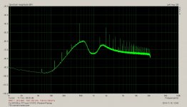
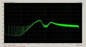
The measurements are taken off the normal monitor output port and meter. The generator is my SVO. The output of the generator is 2.5Vrms and the reference frequency is a nominal 1kHz. The analyzer is set to -90dBV range. The 400Hz and 30kHz filters are engaged except where noted. The spectrum of the monitor port is FFT with an EMU0204 displayed on ARTA. ARTA is calibrated for 1Vrms equals 0dBV FS. The monitor port of the Shibasoku is scaled to 100% of the meter deflection is 1Vrms, (0dBV) on the output of the monitor port. 0dBV on ARTA is -90dBV FS from the 725C normal monitor output port. A 40dBV reading on ARTA corresponds to -130dBV.
The pic below is the 725C monitor port before any mods or upgrades.
The meter reads -117dBV THD+N, ~= 4.5% of 0.003% FS.
The following posts describe modifications to the Shibasoku 725B and 725C distortion analyzer. The Scope of the mods are intended to improve the residual distortion and noise of the normal analyzer section with respect to the normal monitor output port and the front panel meter of the 725C.
The mods are organized in their effectiveness and gains in performance. The mods are simple in nature, simple to carry out and represent close to 100 hours of diagnostics and resolution. The mods include an explanation of the observed fault and resolution. A detailed description of how to carry out the mods and parts involved are provided. Pictures of the boards and spectrum showing before and after results are posted. Some of the mods involve upgrades of op amps, improvement to supply bypassing/isolating and physical rerouting of board grounds. Some of the mods and upgrades have a more profound results than others and these mods are listed first and in order of their effectiveness. However, all of the upgrades have contributed to reduction and improvement of the analyzer's distortion and noise residual. More so from a point of view
of the normal monitor output port and to a lesser degree the meter reading. However for THD+N even what seems a small change can amount to a lot.
In the beggining this 725C measured -117dBV THD+N on the meter and in the end measures -120.9dBV THD+N on the meter and 120.8dBV THD+N on the monitor port according to ARTA and the EMU0204. The meter had quite a bit of dancing around and this has been reduced to an insignificant amount. The meter dance is caused by noise and ingress of signals.
The first three mods have the greatest impact on noise and distortion. The rest is users choice in how far you want to go. The rest of the mods are simply op amp upgrades with some changes to external compensation where necessary.
Some of these mods are mine and some of the op amp upgrades were contributed by 1audio, aka Demian Martin. These mods were carried out with support from Richard Marsh, Dick Moore and Demian Martin. I have also draw from the experience and contributions of other members.
Each mod will be in placed in it's own post. I would like to keep the posts grouped together tightly for easier reference. So I ask that members refrain from comments and remarks until all the mods are posted. I'll let members know when this is complete. Thanks for your cooperation. Any additional mods will be posted at a later date but for now here is what I have.
The measurements are taken off the normal monitor output port and meter. The generator is my SVO. The output of the generator is 2.5Vrms and the reference frequency is a nominal 1kHz. The analyzer is set to -90dBV range. The 400Hz and 30kHz filters are engaged except where noted. The spectrum of the monitor port is FFT with an EMU0204 displayed on ARTA. ARTA is calibrated for 1Vrms equals 0dBV FS. The monitor port of the Shibasoku is scaled to 100% of the meter deflection is 1Vrms, (0dBV) on the output of the monitor port. 0dBV on ARTA is -90dBV FS from the 725C normal monitor output port. A 40dBV reading on ARTA corresponds to -130dBV.
The pic below is the 725C monitor port before any mods or upgrades.
The meter reads -117dBV THD+N, ~= 4.5% of 0.003% FS.
Attachments
A3 board Band Eliminate filter
This mod involves upgrading the feedback amplifier of the first band eliminate filter. This amplifier is known to be sensitive to both noise and distortion in Twin T filters and bridged T filters. Much more so than the filter post amplifier.
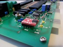
The part to be changed is the QA2 of the A3 BEF board. The original part is a NE/SE5532. This op amp was changed to an OPA1611, one of TI's ultra low noise ultra low distortion op amps with following result.
The second harmonic was originally measured at about -135dBV and after replacement of the QA2 op amp measures about -144.5dBV. That's nearly a 10dB improvement.
The opa1611 is available in an SO8 so a breakout board SO8 to 8DIP is required. I mount the breakout board to a PDIP socket using 20 AWG solid wire. The solder will flow down to the socket pins and bond with the metal. The socket can be directly soldered to the circuit board.
This mod involves upgrading the feedback amplifier of the first band eliminate filter. This amplifier is known to be sensitive to both noise and distortion in Twin T filters and bridged T filters. Much more so than the filter post amplifier.
The part to be changed is the QA2 of the A3 BEF board. The original part is a NE/SE5532. This op amp was changed to an OPA1611, one of TI's ultra low noise ultra low distortion op amps with following result.
The second harmonic was originally measured at about -135dBV and after replacement of the QA2 op amp measures about -144.5dBV. That's nearly a 10dB improvement.
The opa1611 is available in an SO8 so a breakout board SO8 to 8DIP is required. I mount the breakout board to a PDIP socket using 20 AWG solid wire. The solder will flow down to the socket pins and bond with the metal. The socket can be directly soldered to the circuit board.
Attachments

472Hz clock ingress mod
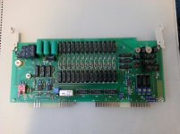
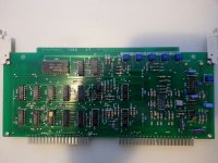
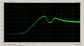
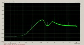
This mod address ingress of local 427Hz clock on the A7 board into the signal path. The clock is used on the A7 and A8 boards for the analog divide circuits. The ingress can be seen on the left dise of the BEF noise curve. The circuits use a proportional DC to pulse width technique to calculate the distortion ratio and is described in the 725B operation manual. The Shibasoku 725 shares a common ground on the back plane with analog and digital circuitry. The circuits use low frequency clocks for the digital portion. The digital circuitry is part of the auto control of the gain and attenuation stages of the analyzer.
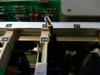
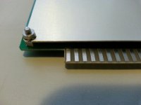
The mod involves cutting the A7 board's ground at the edge fingers on each side of the board. The ground traces are cut between the edge finger and the via above the finger.
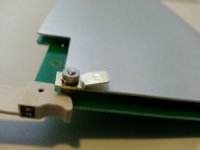
A tab is installed on one of the mounting screws for the shield on the back of the A7 board. A spade connector is attached to a wire which connects to the tab on the A7 board shield. The wire is routed to the COM of the +/-15Vdc power supply. The wire is soldered to a ceramic bead test point connected to the PS COM.
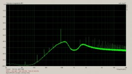
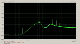
This mod resulted in a 24dBV reduction of the ingress signal. Before and after pics of the spectrum are provided below. The spectrum is taken on the normal monitor port of the 725C. The monitor port is scaled such that -90dBV is equal to 0dBV on the spectrum plot. A -50dBV reading on the plot represents
-140dBV.
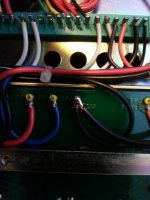
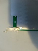
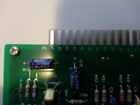
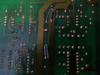
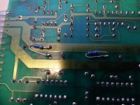
Below are pics of the Shibasoku 725C grounding mod of the A7 board. The TAB is a Keystone 1280, Digikey 1280K-ND. The spade connector is a MU18-250DFK, Digikey 922044-08-ND. A 14 AWG was used but a smaller wire will work just as well. 14 AWG is what was I had on hand. The TAB is angled with an anti rotation grip which helps to cut through coating on the board shield. On the A7 board the shield is removed to carry out the mod. The ground fingers on the top and bottom of the board are cut between the finger and via. This separates the board ground from the back plane ground. The new ground connector is attached to the top rear shield mounting screw. This screw connects directly to the A7 board ground trace. The wire is routed from the A7 board to the power supply COM. The board supports have gap space between the boards. The wire is routed through the gap and onto the power supply. The pics explain the rest.
This mod address ingress of local 427Hz clock on the A7 board into the signal path. The clock is used on the A7 and A8 boards for the analog divide circuits. The ingress can be seen on the left dise of the BEF noise curve. The circuits use a proportional DC to pulse width technique to calculate the distortion ratio and is described in the 725B operation manual. The Shibasoku 725 shares a common ground on the back plane with analog and digital circuitry. The circuits use low frequency clocks for the digital portion. The digital circuitry is part of the auto control of the gain and attenuation stages of the analyzer.
The mod involves cutting the A7 board's ground at the edge fingers on each side of the board. The ground traces are cut between the edge finger and the via above the finger.
A tab is installed on one of the mounting screws for the shield on the back of the A7 board. A spade connector is attached to a wire which connects to the tab on the A7 board shield. The wire is routed to the COM of the +/-15Vdc power supply. The wire is soldered to a ceramic bead test point connected to the PS COM.
This mod resulted in a 24dBV reduction of the ingress signal. Before and after pics of the spectrum are provided below. The spectrum is taken on the normal monitor port of the 725C. The monitor port is scaled such that -90dBV is equal to 0dBV on the spectrum plot. A -50dBV reading on the plot represents
-140dBV.
Below are pics of the Shibasoku 725C grounding mod of the A7 board. The TAB is a Keystone 1280, Digikey 1280K-ND. The spade connector is a MU18-250DFK, Digikey 922044-08-ND. A 14 AWG was used but a smaller wire will work just as well. 14 AWG is what was I had on hand. The TAB is angled with an anti rotation grip which helps to cut through coating on the board shield. On the A7 board the shield is removed to carry out the mod. The ground fingers on the top and bottom of the board are cut between the finger and via. This separates the board ground from the back plane ground. The new ground connector is attached to the top rear shield mounting screw. This screw connects directly to the A7 board ground trace. The wire is routed from the A7 board to the power supply COM. The board supports have gap space between the boards. The wire is routed through the gap and onto the power supply. The pics explain the rest.
Attachments
-
 725 Bottom.jpg534.8 KB · Views: 134
 -
 725 Spade Conn inst.jpg484.5 KB · Views: 146
 -
 725 Tab Top.jpg433.3 KB · Views: 124
 -
 725 top Conn Wire.jpg484.5 KB · Views: 116
 -
 725 Bottom Tab.jpg405 KB · Views: 131
 -
 725 Bottom Finger.jpg425.8 KB · Views: 139
 -
 725 Bot Finger Cut.jpg511.1 KB · Views: 160
 -
 725 A7 Board.jpg603 KB · Views: 181
 -
 727Hz Spike after.JPG250.7 KB · Views: 145
 -
 472Hz ingress.JPG293.7 KB · Views: 178
Last edited:
A2 board clock ingress
This mod involved isolating clock ingress from the A2 board. The clock on the A2 board provides sample pulses to two mono one shots. Together the clock and on shots provide the timing for the auto gain control of the A1 board input amplifier. The clock is formed from a 555 timer IC. The 555 is know to be a bit of a current hog and the ingress is getting into the A1 board via the 15Vdc rail. The is ingress is only noticeable when all the filters except the 400Hz high pass filter is turned off. When all the low pass filter are off the 725C switches in a 750 kHz filter to define the maximum bandwidth of the analyzer in both level and analysis mode. The spikes produced from the A2 board timing are large enough to cause the last gain stage on the A6 board to clip when the analyzer is set to -90dBV range.
The 100kHz and 30kHz filter are enough to attenuate the spike and the effect is not present with these filter engaged.
The fix for this ingress is to cut the pad/via from the main 15Vdc power rail on the A2 board. Insert 100 ohm resistor between the cut away pad/via and main power rail and install caps on the sub rail ends. This provides RC filtering of the 15Vdc rails. The capacitor used for the rail supplying the 555 timer is a 6.8uF OSCON cap. The second rail supplies the rest of the logic ICs on the A2 board. Some of these ICs drive darlington drivers on the A1 board which activate the relays. The drivers require larger instantaneous current
so a larger 330uF electrolytic was used here.
The circuit appear to function fine with the RC rails circuit install. However the 100 ohm resistors can be reduced in value and larger cap values used if any problems should arise. I haven't noticed any yet. The smallest resistor in the timing circuit is 47k. 100 ohms on the rails will have little impact on the timing.
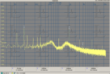
The result is a near 30dBV reduction in noise.
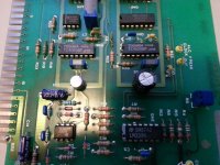
Below is the before and after pics and shots of the board mods.
The scope shot is the spike noise measured off the monitor port.
This mod involved isolating clock ingress from the A2 board. The clock on the A2 board provides sample pulses to two mono one shots. Together the clock and on shots provide the timing for the auto gain control of the A1 board input amplifier. The clock is formed from a 555 timer IC. The 555 is know to be a bit of a current hog and the ingress is getting into the A1 board via the 15Vdc rail. The is ingress is only noticeable when all the filters except the 400Hz high pass filter is turned off. When all the low pass filter are off the 725C switches in a 750 kHz filter to define the maximum bandwidth of the analyzer in both level and analysis mode. The spikes produced from the A2 board timing are large enough to cause the last gain stage on the A6 board to clip when the analyzer is set to -90dBV range.
The 100kHz and 30kHz filter are enough to attenuate the spike and the effect is not present with these filter engaged.
The fix for this ingress is to cut the pad/via from the main 15Vdc power rail on the A2 board. Insert 100 ohm resistor between the cut away pad/via and main power rail and install caps on the sub rail ends. This provides RC filtering of the 15Vdc rails. The capacitor used for the rail supplying the 555 timer is a 6.8uF OSCON cap. The second rail supplies the rest of the logic ICs on the A2 board. Some of these ICs drive darlington drivers on the A1 board which activate the relays. The drivers require larger instantaneous current
so a larger 330uF electrolytic was used here.
The circuit appear to function fine with the RC rails circuit install. However the 100 ohm resistors can be reduced in value and larger cap values used if any problems should arise. I haven't noticed any yet. The smallest resistor in the timing circuit is 47k. 100 ohms on the rails will have little impact on the timing.
The result is a near 30dBV reduction in noise.
Below is the before and after pics and shots of the board mods.
The scope shot is the spike noise measured off the monitor port.
Attachments
Last edited:
Op amp upgrades to A4, A5 and A6 boards
The following is a list of op amp upgrades on the A4 BEF board, A5 BEF board and A6 board.
The A6 board has two of the gain stages and filter circuit on board. Although there was impact to distortion reduction the upgrades did help to reduce the noise residual of the analyzer.
On the A4 BEF board the feedback amp QA2 is replaced with an LME49990.
On the A5 BEF board the feedback amp QA2 is replaced with an LME49990.
On the A6 board QA1 OPA2134, QA2 LT1468 with C102 removed and FB cap of 7pF
installed. QA4 OPA2134, QA3 LT1468, QA5 LT1468 with 7pF FB cap installed.
On the A4 board QA5 is replaced with LME49710. This will be an LME49990 but I'm out of breakout boards. C47,C43, R63 are removed.
R64 is changed to 600 ohm and R61 to 66 ohms, C44 is removed. R62 is removed and replace with a jumper. On the 725C this R62 is already done by Shibasoku. R60 may need adjustment to make up for the the low R of the LME op amp. The LME49990 places a 20k ohms in parallel with R60. This will undoubtedly effect the level gain.
This concludes the mods and op amp upgrades.
I'll post any further upgrades another time.
Cheers,
Last edited:
725 has somewhat different limitations
My much earlier 725 has somewhat different limitations. it does not have some of the filter circuits and I think the timing on the metering AGC is different. Here is what I get using the Viktor oscillator (an early example). This unit only has the A3 opamp mod and some buffer amp upgrades on the A1 board so far. If time permits I'll go through and do the other mods as appropriate.
I think this first gen shows the core performance that was compromised a little to add the other features. While the differences show this way it more than met spec in the original form and even with the additional features the problems did not really show on the meters.
I do need to replace the main filter caps on both he 725 and the matching oscillator. 30 years is a reasonable lifetime for them.
Attachments
The measurments I just posed were after 15 minutes of operation. I think this one gets a little better after running for a while but even the ambient EMI seems to effect the performance, with the best late at night or early in the AM. Grounding is the bigger challenge.
I will be moving to a new shop in about a month where I'll be readdressing a lot of these issues.
I will be moving to a new shop in about a month where I'll be readdressing a lot of these issues.
- Home
- Design & Build
- Equipment & Tools
- ShibaSoku Automatic Distortion Analyzer