I decided that it could be interresting to investigate the "nature" of the tweeter response further with the aim to see if the anomality, in particular that 13k dip was only the result of a particular measurement (mic position) or if it is a problem consistently present throughout the sound-field.
I therefore did a series of off-axis measurements and some vertical ones.
All the horizontal off-axs measurements were made with the mic pointing between the woofer and the tweeter.
The measurements are allso done with the current HP shelf in place.
The turn-table I use doesn't allow me to have the axis of rotation coincide with the plane of the baffle, so as the loudspeaker was rotated, the microphone didn't point directly at the acoustic centre of the speaker any more. But for relative measurements, I assume this is OK.
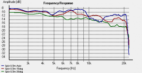
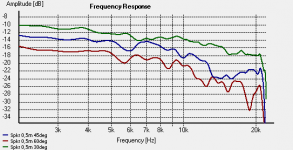
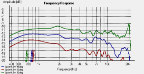
As I can only display 3 measurements at a the time in Holm Impulse, I have split the measurements in to twoo images.
The first shows 0, 15, and 30 degrees, the second shows 30, 45, and 60 degrees
It should be obvious which curve is which.
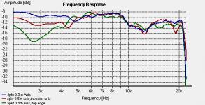
The last image is on Horizontal axis, but with the mic pointing between woofer and tweeter (blue), on tweeter axis (red), upper edge of speaker (green)
The vertical measurements doesn't show that much change, but they were only made over a limited range. Having said that, the measurement with the mic pointing towards the uper edge of the box seems to have a more even level.
Looking at all thes measurements under one, it seems to me that there is no consistent peak or dip throughout the horizontal plane that can or should be targeted with a trick filter, and that on average the best thing to do would be to simply increase the shelving High pass gain 2-3 dB more.
What do you think?
I therefore did a series of off-axis measurements and some vertical ones.
All the horizontal off-axs measurements were made with the mic pointing between the woofer and the tweeter.
The measurements are allso done with the current HP shelf in place.
The turn-table I use doesn't allow me to have the axis of rotation coincide with the plane of the baffle, so as the loudspeaker was rotated, the microphone didn't point directly at the acoustic centre of the speaker any more. But for relative measurements, I assume this is OK.
As I can only display 3 measurements at a the time in Holm Impulse, I have split the measurements in to twoo images.
The first shows 0, 15, and 30 degrees, the second shows 30, 45, and 60 degrees
It should be obvious which curve is which.
The last image is on Horizontal axis, but with the mic pointing between woofer and tweeter (blue), on tweeter axis (red), upper edge of speaker (green)
The vertical measurements doesn't show that much change, but they were only made over a limited range. Having said that, the measurement with the mic pointing towards the uper edge of the box seems to have a more even level.
Looking at all thes measurements under one, it seems to me that there is no consistent peak or dip throughout the horizontal plane that can or should be targeted with a trick filter, and that on average the best thing to do would be to simply increase the shelving High pass gain 2-3 dB more.
What do you think?
Attachments
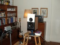
What you are seeing is most likely diffraction, I believe. The position at which you have mounted the tweeter is close to being equidestant from the top edge and the sides of the cabinet, which encourages these types of problems. Even worse, your "foam" sheet with the drivers screwed on to them (to eliminate routing as you say) seems to have created a "ringed depression" around the tweeter flange which looks to be about 5-7mm deep, judging by the picture. If so, this is bad news. Even though it is not a sharp edge, you can probably still get diffraction off of this surface or reflections back in to the horn.
Here's how you can diagnose these problems:
1. Remove the tweeter from the speaker cabinet but keep it connected (or reconnect it via some extra lengths of wire) to the crossover.
2. Find a large piece of cardboard, e.g. at least 0.5m x 0.5m, the bigger the better.
3. Cut a hole in the cardboard and "mount" the tweeter in it (not yet flush mounted).
4. Take frequency response measurements of this, on axis (and off axis if you would like).
5. Now "flush mount" the tweeter. Find some solid material (like more cardboard, but not foam or felt) that is the same thickness as the tweeter flange. You want to use it to create a "flush like" surface around the tweeter flange. You could use the first piece of cardboard, and then you just need a small piece to mount the tweeter on and stick it on the back of the first piece so that the flange is flush with the large surface.
6. Now remeasure.
This will give you an idea of what the tweeter response is like without cabinet diffraction. The cardboard is plenty stiff and large for a tweeter's pressure wave to be essentially an infinite plane, e.g. 2PI space. Since the crossover is still connected, you can be assured that you are still measuring its effect.
The difference between what you measure when the tweeter is flush mounted in the large cardboard, and what you have measured in your speaker, is the diffraction signature. You may find that this is the source of your problem. If that's true, you can cut the cardboard down to a size that is the same as the front of the speaker, with the tweeter positioned in the same location but now flush mounted in the cardboard, to see what you will get if you change the mounting to true flush mounting in the cabinet.
Hopefully that will shed some light on how to possibly fix your response issue. If not, post the results and we can look for other problems. Luckily you have a good measurement system, so you can discover and diagnose these issues!
-Charlie
P.S. Here's Mark K's 2-way using the DXT tweeter, with a similar mounting position:
http://www.audioheuristics.org/projects_gallery/ER18DXT/ER18DXT.htm
The tweeter is flush mounted. Since there is no major diffraction signature from his baffle, I am thinking that the "ring" in the foam around the tweeter may be the culprit in your case...
Last edited:
Charlie,
A very interresting reply there..
Just as a quick check, I attached some old printed circuit boards (without components), on each side of the tweeter to se if that made any difference.. very little.. I allso placed a thick book on top of the speaker to simulate an upwards extension of the baffle, neglible effect..
But your comment about the depression in the foam creating a possible unintended difraction feature, perhaps like the difraction ridges in the actuall wave-guide, is very interresting..
A bit of a hassle to remove the tweeter with soldered leads and everything, but I could allways try and stick on a piece of cardboard with a cutout just fitting the tweeter, that should at least give some sort of indication..
Now to find some cardboard...
Charlie,
Hats off to you!
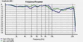
I found some cardboard.. did a precise cut and attached it with tape..
I guess the graph says it all.. blue is the original measurement, green is with the cardboard..
I must admit that I'm surprised that that depression had such an effect!
As it looks like now, All I need to do is to bump the shelving filter gain up about 3 dB.
But.. what the £$€$@€!! am I going to do about that groove!?
The foam is glued quite firmly to the baffle, and even with that gone, routing would be impossible as The holes have allready been cut in the baffle..
Hats off to you!
I found some cardboard.. did a precise cut and attached it with tape..
I guess the graph says it all.. blue is the original measurement, green is with the cardboard..
I must admit that I'm surprised that that depression had such an effect!
As it looks like now, All I need to do is to bump the shelving filter gain up about 3 dB.
But.. what the £$€$@€!! am I going to do about that groove!?
The foam is glued quite firmly to the baffle, and even with that gone, routing would be impossible as The holes have allready been cut in the baffle..
Attachments
Last edited:
Well,
As I had nothing to loose, I took a sharp hobby-knife to the foam and made a cut arround the tweeter.
As the foam has been compressed by the tweeter flange for some time, it remains to see if it will swell back and give a proper flush against the tweeter.
There was some initial "swell-back" after I cut, and that alone was enough to improve the 13k notch by about 1 dB.
If the foam doesn't recover, I could allways get some new foam sheets and make a similar cut before screwing the tweeters home flush propperly.
It will be interresting to see what happens over night..
Well,
As I had nothing to loose, I took a sharp hobby-knife to the foam and made a cut arround the tweeter.
As the foam has been compressed by the tweeter flange for some time, it remains to see if it will swell back and give a proper flush against the tweeter.
There was some initial "swell-back" after I cut, and that alone was enough to improve the 13k notch by about 1 dB.
If the foam doesn't recover, I could allways get some new foam sheets and make a similar cut before screwing the tweeters home flush propperly.
It will be interresting to see what happens over night..
Glad I was able to get you going in the right direction.
-Charlie
You certainly did Charlie, I seriouslu doubt that I would have identified that issue my self! ")
Doesn't look like that foam is recovering properly, so I'll change the foam for new and "countersink" with the knife.
A bit of a hassle, but considering the very good frequency response obtained aside from this problem, it would be a shame to let that one anomality ruin it all.
Doesn't look like that foam is recovering properly, so I'll change the foam for new and "countersink" with the knife.
A bit of a hassle, but considering the very good frequency response obtained aside from this problem, it would be a shame to let that one anomality ruin it all.
Finally, time to present a result...
After chasing round half of Oslo in order to obtain a fresh supply of Armaflex foam, I got new foam fronts in place and got the tweeters countersunk propperly.
As with the experimental "cardboard baffle", the 13k dip was gone.
I then went about with the shelving High pass filter to hammer out a reasonably flat response.
I ended up with a 12 dB/Oct curve with F1 of 4500Hz and F2 of 12680Hz and a total gain of 18 dB (!), i.e. 9dB gain in each of the two 6dB/oct filters I connected in series.
It surprised me a bit that I had to apply such brutal correction, but now I got a frequency response which is allmost +/- 1 dB flat up to 17k Hz. on axis.
(This is of course with some assumptions regarding my amateur measurement set-up)
As can be seen from the attached plot, the trade-off is a 4 dB peak above 17k. The sloping curve is without any HF shelving EQ at all.
I guess it's a few years since I could hear frequencies in that range, so unless I wake up as a dog one day, this is a trade-off I can live with!
So again; super-thanks to Bob for telling me how to do a 12dB/oct shelving filter and Charlie for pointing out the unintended "difraction groove" arround the tweeter!
Thanks to you, what looked like ending up as a bit of a lackluster design has been rescued!
I'll see if I can round this off with a series of off-axis measurements as well.
Attachments
So,
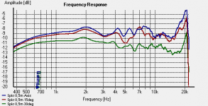
Here's the off-axis plots in 15 deg. increments from 0-60.
As with the previous off-axis measurements, the axis of rotation is not perpendicular with the acoustic axis, so same offsett situation.
Anyway, I think this looks reasonably OK?
Here's the off-axis plots in 15 deg. increments from 0-60.
As with the previous off-axis measurements, the axis of rotation is not perpendicular with the acoustic axis, so same offsett situation.
Anyway, I think this looks reasonably OK?
Attachments
Looks pretty good. You might look into a 6 dB shelf or first order filter to knock down that peak at the top end.
I can't hear a pure tone up that high anymore, but peaks like that still annoy me. Kids thought I couldn't hear their mosquito ringtone, but I did. A friend had an "Ultrasonic" anti barking device for his dog that drove me nuts. Still, I can't hear a 15 KHz pure tone but I do sense it to a degree as pressure.
I still wonder about the top end of your measurements being so different from Mark K's. How do your speakers sound? Not a little bright?
Another filter?!
I'm running out of op-amps on my card here..
Well,
The speaker do perhaps sound a bit on the bright side, but then again ,I allso have a high pass filter giving a -6dB of 70Hz, so there is not much bass to balance. (subwoofer under construction!)
Allthough bright, not at all unpleasant to listen to, just clear and nice with no "sharp edges" or anything.
The measured response is measured midway between woofer and tweeter, so on-tweeter-axis response will of course be brighter..
Good point about that anti-barking device.. and assuming it had a high energy density at high frequency it might well be quite noticeable, as you say, what one can sense and hear/ distinguish clearly might be two different things.
In addition to my naturally reduced HF capability, the spectral density at 17+k on recorded material is usually not that high anyway, so I think I'll leave it as is rather than trying to squeeze in yet another filter.
I agree that the difference in response to Mark's speaker (and some other designs) is a bit peculiar..
I guess the placement of the tweeter/ baffle dimensions might play a part. Allso, that foam front might absorb some high frequencies? Allthough it is a closed cell foam, it is really dead stuff, even more "squidgy" than the stuff they make ear-plugs from.
Last edited:
Are you really measuring at .5m? Do you intend these for nearfield use? If not, try moving back a bit 1-2 meters might give you a different picture.
If that hi frequency peak doesn't bother you leave it alone. If you feel something isn't quite right after extended listening, just remember that the peak may be annoying you.
I'm really surprised that the waveguide didn't prevent interaction with the foam at such high frequencies. I guess it really is more of a diffractor that spreads the sound field than a waveguide.
Yes, I'm measuring at 0,5m, but It doesn't hurt to try at 1m or 2m (if I have enough space in my small living-room)
The speakers will be for "normal" home-stereo use , not nearfield.
My understanding of the DXT tweeter is that it is both a wave guide limiting dispersion at lower frequencies and a difractor (the ridges/ steps in the wave-guide) increasing dispersion at higher frequencies.
Oh, by the way, I made an error in one of my previous posts.. the F1 ended up at 6730 Hz and F2 at 19200 Hz.. I had the wrong capacitance value in the spreadsheet! Not that this changes the result, but for the sake of correctness and to avoid misguiding other readers of the thread..
As it looks now, I have one dual op-amp "left" on my card, so I could allways use it for a 24dB oct. low pass to cut that peak if required.. But before considering that further, I think I will do some more listening with the speaker in a "normal" placement and then see.
For any future projects, I think it will be a good idea to do some practical tests with different baffle dimensions and tweeter positions, not to mention any surface treatments, before going ahead and building boxes.
Well,
Seems I'll have to get back on this one..
As you said Bob, extensive listening..
Something isn't quite right.
I've finally completed one out of two subwoofers, so now I have one channel up and running full range. The sub is a 150L closed box with a Dayton RSS380 15" woofer, so now I have all 10 octaves covered!
I wouldn't describe the sound as bright, morte like thin in a way.
This is quite noticeable on cymbals, both crash- and ride. there seems to be plenty of "Fssh", but the sound and body of the brass seems to be lacking..
I'm really starting to think that the 15-20k peak is perhaps more of an issue than I first assumed...
Looking at the frequency plots, what sort of filter/ slope would be best suited to attack this peak without messing things up further down?
I have so far assumed that a flat frequency response is the ideal, and disregarding the HF peak, I feel I have come close to this.
Having said that, I feel that some body and presence is perhaps lacking a bit.
Could this again be a consequence of the HF peak, or should I perhaps reconsider the balance of the overall frequency response?
Now, I'm not after "EQ'ing" my records through my loudspeakers, but something that will give a realistic and satisfying sound reproduction in my domestic listening environment.
I'm starting to slip on the slippery slope of subjectivity here with not too much speaker or filter design experience to draw on, so any nudge in the right direction is greatly appreciated!
Rolling off the top end with a 17 Khz low pass might help.
Body and presence are usually associated with lower frequencies, though. You seem to have a bit of a peak around 2K, which could seem to depress the presence region below it. It looks a bit too high to be a diffraction effect due to baffle width.
Where are you crossed to the DXT?
Have you done a measurement with the tweeter reversed? Did you get a nice deep null?
Guessing you are crossed over a little under 2K, You might try padding down the tweeter around 1-1.5 dB, it looks like it could give you a nice BBC dip and take care of the slight brightness.
You might also run Room EQ Wizard, to ensure that your transition to the sub is proper. Some thin-ness might be associated with a gap in response - the mains rolling off a bit too much before the sub kicks in.
Last edited:
Bob,
I'll try some other shelving filter curves first, some that doesn't give that pronounced 15 k peak (allthough this is most likely to give a less flat overall response ). If that makes things more pleasant, I can change back and throw inn a 17k low pass as you suggest.
The DXT is crossed relaitvely high actually, 2500 Hz 24 dB/Oct.
In order to get a nice overlap from the SEAS W17cy woofer, I actually had to move the low pass frequency up from 2500Hz to 3200Hz! This surprised me a bit, and seems to go a bit against the "convention" in many ways, but looking at the plots, it seems to work!
When reversing tweeter phase I get a 10dB dip around the x-over frequency. I guess the null could be both deeper and narrower, but then again, that would just mean deeper and sharper nulls in the vertical polar response.
Hmm what's a BBC-dip again? I've heard the term before, but I can't really remember what it involves??
Crossed that high, I bet what you are hearing is the woofer breakup modes. Crossed that high I doubt that they are more than 10-20 dB down. Try pushing the crossover down to 1800 or so as a target. Even then, you probably need a notch to kill woofer breakup, and take it down -40-50 dB.
Can you post individual driver raw and filtered response? Measure out at 1M or so.
That top end peak is in the driver's raw response, a little lower than published. You should be able to flatten the response with a 1st order shelf centered around 9 Khz (6K to 12K), then roll off or notch out the peak.
I think the deeper the notch with the tweeter reversed is an indicator of better phase matching. Using Frequency Allocator I was able to try various crossovers and ended up liking the sound of the deepest notch best. Another experiment showed flatter vertical polar response with a phase corrected MTM than without correction. Totally unscientific pink noise and move up and down at close range, noticing less picket fencing.
With a TM you'll probably find less of an issue with vertical lobing as long as you keep the main lobe pointed at the listening position. It would seem worse at .5 M than 1-2M, since the angular separation of the drivers is greater in close.
BBC dip is a slight dip in response centered somewhere around 2.5Khz.
Bob,
Your comment on woofer break-up modes is interresting.
Looking at the SEAS data sheet http://www.seas.no/images/stories/vintage/pdfdataheet/e002.pdf, the W17cy doesn't seem to be horrendous in that respect, but I might well have underestimated the possible issue with this.
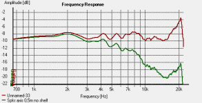
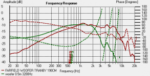
Enclosed, you see a plot with the raw response of the woofer taken from 190cm (did this last year in a warehouse at work so I could get some distance from adjacent surfaces), and a measurement with 3200 Hz x.over and BSC taken at 50 cm in my living room.
I thought this looked relatively OK with only a modest peak around 5 k noticeable.
I added phase response in the plot, hope this doesn't clutter things up too much!
My idea was to divide the midwoofer as high as possible without off-axis problems or breakup so as to move the x-over region outside the critical 200-2000 Hz area where the ear is most sensitive and uses time differences to locates sources. I had hoped that 24 dB /Oct filtering would allow me to push the x-over point higher than what would be OK with a more conventional 12 dB/Oct filter.
This was of course only an idea, and I might well have missed something.
Regarding reverse polarity Notch, it sounds very sensible to have matched phase in the crossover region. The linkwitz board I'm using for the filter has a configuration for an "allpass" filter for modifying phase, so this is perhaps something I should investigate closer...(but then I won't have any op-amp left for filtering out the 15k peak)
But first things first.. does the filtered woofer response look usable, or am I way off here??
Your comment on woofer break-up modes is interresting.
Looking at the SEAS data sheet http://www.seas.no/images/stories/vintage/pdfdataheet/e002.pdf, the W17cy doesn't seem to be horrendous in that respect, but I might well have underestimated the possible issue with this.
Enclosed, you see a plot with the raw response of the woofer taken from 190cm (did this last year in a warehouse at work so I could get some distance from adjacent surfaces), and a measurement with 3200 Hz x.over and BSC taken at 50 cm in my living room.
I thought this looked relatively OK with only a modest peak around 5 k noticeable.
I added phase response in the plot, hope this doesn't clutter things up too much!
My idea was to divide the midwoofer as high as possible without off-axis problems or breakup so as to move the x-over region outside the critical 200-2000 Hz area where the ear is most sensitive and uses time differences to locates sources. I had hoped that 24 dB /Oct filtering would allow me to push the x-over point higher than what would be OK with a more conventional 12 dB/Oct filter.
This was of course only an idea, and I might well have missed something.
Regarding reverse polarity Notch, it sounds very sensible to have matched phase in the crossover region. The linkwitz board I'm using for the filter has a configuration for an "allpass" filter for modifying phase, so this is perhaps something I should investigate closer...(but then I won't have any op-amp left for filtering out the 15k peak)
But first things first.. does the filtered woofer response look usable, or am I way off here??
Attachments
That breakup peak is only 24 db down - It's nowhere near as bad as some but still quite audible. It also makes your effective slope on the woofer only ~2nd order. If you were to notch it down ~13 dB you'd have a 4th order slope. I'd still take it a little deeper, but that's me who likes quasi 8th order elliptical filters.
Notice how Seas' off axis response is seriously beaming by 2K? I think the "keep the XO out of the 200-2,000 area came from the prevalence of improperly implemented crossovers mucking things up in the dark ages before we understood the importance of power response. You're going to properly implement this XO. Head down to 1,500 Hz or so. Linkwitz did it with the Orions and it worked out quite well by most accounts.
What boards are you using? The Jens Rasmussen group buy boards, SL's or some other? Phase correction can be accomplished with split crossover frequencies, split orders, all pass filters or a combination of them. SL seems to feel it's easier to use the all pass than try to split the XO frequencies.
Notice how Seas' off axis response is seriously beaming by 2K? I think the "keep the XO out of the 200-2,000 area came from the prevalence of improperly implemented crossovers mucking things up in the dark ages before we understood the importance of power response. You're going to properly implement this XO.
Head down to 1,500 Hz or so. Linkwitz did it with the Orions and it worked out quite well by most accounts.What boards are you using? The Jens Rasmussen group buy boards, SL's or some other? Phase correction can be accomplished with split crossover frequencies, split orders, all pass filters or a combination of them. SL seems to feel it's easier to use the all pass than try to split the XO frequencies.
Last edited:
I'm using the Linkwitz lab MT1 boards.
Tey're not tailored to my application, but so far I've managed to use them for the following:
Baffle step correction
Sub low-pass, 70Hz 24dB/Oct
"satellite" adjustable gain
Satellite high-pass, 70Hz 24 dB/Oct (using op-amp intended for allpass filter)
HF shelving EQ, 12 dB/Oct
satellite Midwoofer lowpass 24 dB/Oct
satellite tweeter adjustable gain
satellite tweeter High pass 24dB/Oct.
One dual op.amp after the tweeter highpass unused (on card this is intended for an allpass filter)
I will of course use one card for each stereo-channel. Got them second-hand but unused on the forum a good while ago.
From what you're saying, my woofer x-over point allows some significant break-up garbage at audible levels. The resulting overall frequency response looks OK, but apparently for the "wrong" reasons..
Your point about the break-up nodes giving me a 2nd order slope in stead of a 4th order explains why i had to pull the x-over point up from 2500Hz to 3200 Hz in order to get flat summation with the tweeter crossed over at 2500 Hz.
Due to the constraints of my cards, I feel a bit hesitant about applying a notch to take on the break-up nodes. But If i follow your recommendation and cross the woofer over at 1800-2000Hz, this may yet reduce the significance of the breakup nodes sufficiently?
Since I'm using 4th order filtering on the tweeter, I assume it will be OK to pull down the x-over frequency here to meet the midwoofer without any distortion/ overload issues?
My thoughts on keeping x-over frequency outside the 200-2000Hz area was simply based on the assumption that the less that goes on in this region x-over wise, the better. I'm thinking that crossing over in this area makes it possible to "separate" signals from the woofer and the tweeter as originating from separate sources due to the ears time/phase sensitivity in this area. allthough I believe this philosophy to be of some validity, I might well be assigning it importance which is not of significance compared with other issues. On the other hand, lowering the x-over frequency will diminish the significance of midwoofer-tweeter spacing in terms of time/ phase criticality..
I guess my "high x-over frequency" philosophy would be better employed with a smaller midwoofer with higher breakup frequency and less beaming, but then again, such a smaller midwoofer (4-5") would perhaps have issues with midbass performance and crossing over to the subwoofers..
Well, time to power up the soldering-iron and reduce the midwoofer x-over frequency to somewhere under 2000Hz I guess!
- Status
- This old topic is closed. If you want to reopen this topic, contact a moderator using the "Report Post" button.
- Home
- Source & Line
- Analog Line Level
- Shelving 2nd order high-pass?