Great!norazmi said:
Also to LUKA, hi there your offline smps still running with good condition
norazmi said:Hi N. Channel,
....Vcc is 12V from batt right?
Yes, from 12V Battery Supply.
norazmi said:Ive seen on output schematic there is lots of irf1404 mosfet so can i just make it 4 of them, ie. irfz44N? because i just need 300 watts only.... and at output mosfet is IRFP250N i would change to IRF740 4 pcs is ok with it? because i would have 240 vac at output. About the ics tl494 is ok for me i`ve it on my hand, but as you mention it can be change to SG3525AN without any adjustment? i mean for the pin leg.
And what the function for VR1 and VR2 ? freq control?
IRFZ44n should do fine. IRFP250N is for 120VAC output. The IRF740 (Vdss = 400V) is appropriate for 240VAC out.
SG3525 is NOT a drop-in replacement. Obviously, there are some component- & value changes that will need to be made, but, for the most part, it should work OK.
VR1 controls output frequency (in this case 120Hz), you will want to adjust it for 100Hz.
VR2 is for sensing the 120VAC output to provide for voltage regulation.
norazmi said:Thanks N. Channel for the schematics i`ll study and try to make pcb for it, i think it would take long time for me to design it, but i`ll try to make it work. If you willing to give me sample of the control pcb it would save my time to make it work and running.
Sorry, this is not my design. I did not do the pc boards, and have no access to the patterns. It is an AIMS 2.5kW model that was given to me as DOA, and I am trying to resurrect it.
norazmi said:Best Regards,
Azmi.
[/B]
Sinewave Inverter
hi all
I would like to make a suggestion and request everyone to comment on my idea
its not a new one I seen it implemented in Motor Inverters all the time
they use a higher frequency like 29KHZ and then sinewave is modulated on it, can this be used in making Inverters to be used on Home Appliances.
Re: Sinewave Inverter
Fahim,
The OLD sinewave inverters of years gone by used to run the transistors in the output stage in a true linear sinewave fashion at a constant 50/60Hz. This was just fine for cleanliness of signal, but terrible for efficiency, because their transistors were essentially being run as a BIG class-AB amplifier stuck at 50/60Hz, and they dissipated a LOT of heat. There had to be a better way, and there is: just what you posted. In fact, the only way companies like Xantrex, who make really nice sinewave inverters (they also make the more conventional modified-sinewave units, too), can squeeze over 3kW of nice, clean 120- or 240V sinewave AC power is through the use of a high-frequency PWM, modulated at 50/60Hz.
RX5,
Haven't hooked it up in a while. Not even sure where it is. If I find it soon, I'll try to copy output signal fron IC2.
Cheers for now,
Steve
fahimbaig said:hi all
I would like to make a suggestion and request everyone to comment on my idea
its not a new one I seen it implemented in Motor Inverters all the time
they use a higher frequency like 29KHZ and then sinewave is modulated on it, can this be used in making Inverters to be used on Home Appliances.
Fahim,
The OLD sinewave inverters of years gone by used to run the transistors in the output stage in a true linear sinewave fashion at a constant 50/60Hz. This was just fine for cleanliness of signal, but terrible for efficiency, because their transistors were essentially being run as a BIG class-AB amplifier stuck at 50/60Hz, and they dissipated a LOT of heat. There had to be a better way, and there is: just what you posted. In fact, the only way companies like Xantrex, who make really nice sinewave inverters (they also make the more conventional modified-sinewave units, too), can squeeze over 3kW of nice, clean 120- or 240V sinewave AC power is through the use of a high-frequency PWM, modulated at 50/60Hz.
RX5,
Haven't hooked it up in a while. Not even sure where it is. If I find it soon, I'll try to copy output signal fron IC2.
Cheers for now,
Steve
N-Channel said:Luka-
I may have made a mistake, I think it is 100Hz. Sorry.
Azmi-
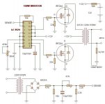
See the two attached schematice on a 2.5kW Inverter. First one is DC-DC boost converter driven by TL494. This can be easily changed to an SG3525, and it might be easier because of the '3525's outputs being totem-pole. The second schematic is of the DC-AC Inverter, driven by a second TL494, programmed to run at 120Hz (2 x 60Hz).
This should clear a few things up.
Hello
Looking at your 2500w inverter schematic, GP-12-2500 are Genius brand and are made by DROW ENTERPRISE CO., LTD.
You was lucky to find those Genius inverter schematic, my Xantrex inverter schematic was impossible to find.
http://www.genius.com.tw/index.asp
http://www.genius.com.tw/product_list.asp?SerialNo=46&divIndex=3&divNum=maindiv3&treeNum=div3sub1
I have a burned 1750w Xantrex Xpower Plus inverter (rebranded as Motomaster), plus 4 more of the same transformer like those in my Xantrex inverter, can I use those 8 transformers to made the 2500w inverter from your schematic ?
I have some IRF640 but they are not enough power for that 2500w inverter, so I may need to paralllel them.
I also have few TL494 chips.
I include photos of the inside of my 1750w Xantrex inverter.
Thank a lot
Bye
Gaetan
An externally hosted image should be here but it was not working when we last tested it.
An externally hosted image should be here but it was not working when we last tested it.
An externally hosted image should be here but it was not working when we last tested it.
Help with troubleshooting Xantrex Xpower 1500
Hi
I stumbled across this site and thread and am thrilled with what I see.
I have an Xantrex Xpower 1500 with some damage.
When switched on the RED fault LED comes on but the GREEN power LED does not.
I have downloaded the representative schematics for this device class posted earlier in this thread and would appreciate some guidelines for troubleshooting.
specifically....
1. what conditions trigger fault indication.
2. where fault indicator is driven from (it has TL494 and KA 7500B regs)
There is no output.
It may have suffered input overvoltage from solar panel when batteries overcharged.
Thanks for any help and keep up the good work
Don
xantrex 1500w
Don, do you have a schematic for the inverter? If so, could you e-mail it to 71240z@cox.net
I have a continuous fault light and the fans spin for about 1 sec. Trying to troubleshoot.
Thanks, Craig
Don, do you have a schematic for the inverter? If so, could you e-mail it to 71240z@cox.net
I have a continuous fault light and the fans spin for about 1 sec. Trying to troubleshoot.
Thanks, Craig
than tang anh emN-Channel,
What are the Part #'s for the two IC's (U-1 & U-2) in the control circut diagram?
Thank You,
Attachments
Want the Xantrex's scheme XPower 1500 where himself horseradish all his parts including the diodes than be near by the fusesHello
Looking at your 2500w inverter schematic, GP-12-2500 are Genius brand and are made by DROW ENTERPRISE CO., LTD.
You was lucky to find those Genius inverter schematic, my Xantrex inverter schematic was impossible to find.
DROW ENTERPRISE ³Ç«W¬ì§ÞªÑ¥÷¦³¤½¥q
DROW ENTERPRISE ³Ç«W¬ì§ÞªÑ¥÷¦³¤½¥q
I have a burned 1750w Xantrex Xpower Plus inverter (rebranded as Motomaster), plus 4 more of the same transformer like those in my Xantrex inverter, can I use those 8 transformers to made the 2500w inverter from your schematic ?
I have some IRF640 but they are not enough power for that 2500w inverter, so I may need to paralllel them.
I also have few TL494 chips.
I include photos of the inside of my 1750w Xantrex inverter.
Thank a lot
Bye
Gaetan
An externally hosted image should be here but it was not working when we last tested it.
An externally hosted image should be here but it was not working when we last tested it.
An externally hosted image should be here but it was not working when we last tested it.
project work
pls am working on a switch mode 1kva inverter,from given block diagram,its includes; 12volt dc source,oscillator (sg3524 @50khz pulse),mosfet swiches,ferrite core transformer (12V/350V @ 50KHZ),Rectifier,modulator,mosfet bridge,filter,wit an output of 230V @ 50HZ.i av bin able to work up to the switch but i rili dont no hw to go abt d transformer (no material,u can just help me post any material on it), also i dont no d component and d function of d Rectifier,modulator, and d mosfet bridge.also hw can i b able to achieve my desired output,pls i nid detailed explaination.
pls am working on a switch mode 1kva inverter,from given block diagram,its includes; 12volt dc source,oscillator (sg3524 @50khz pulse),mosfet swiches,ferrite core transformer (12V/350V @ 50KHZ),Rectifier,modulator,mosfet bridge,filter,wit an output of 230V @ 50HZ.i av bin able to work up to the switch but i rili dont no hw to go abt d transformer (no material,u can just help me post any material on it), also i dont no d component and d function of d Rectifier,modulator, and d mosfet bridge.also hw can i b able to achieve my desired output,pls i nid detailed explaination.
hi,
i want to make an inverter in order to use it at a diy ups for my pc...
i think that with 400 wattw i will be fine...
i want a swich mod inverter...
can you help me find a circuit?
i saw the 2.5 kw inverter circuit but it's to big for my needs and for the knowlege i have at elektronics...
i think i need a true sinewave inverter to run the pc...
can you help me?
i
- Status
- This old topic is closed. If you want to reopen this topic, contact a moderator using the "Report Post" button.
- Home
- Amplifiers
- Power Supplies
- SG3525 for Inverter