Hello,
Just registered and say hello to everyone here in the forum.
In response to steph_tsf and for your information I own
- 4 pair of servo-sound Type 15 B speakers
- one servo-sound preamplifier type PA5
- one servo-sound stereo crossing box , not type SC2
I finished to replace all electrolyt capacitors : in the preamp as well as in 2 speakers,
and are giving them a try soon.
Hi,
I hope someone can help me.
I cannot run the servo-sound simulation files I have an issue with the MJE15030/1 that do not seem to exits despite the custom lib and if they replaced by generic components the analysis runs for like ever.
I have tried to manually edit the net list to include the custom lib by adding .include my_own_npn_pnp_bjt_v402.lib. This gets rid of the MJE15030/1 error but the analysis still runs for ever.
When I press ESC LTspice displays: “failed to find dc finding operating point for AC analysis".
I am sorry if it is a noob question but I am a noob with LTspice (I am a killer at Matlab though). I was however successful in running the Philips models. It seems to me that the issue is in the power amp itself?
Cheers
Mickael
Regarding the servo-sound :
Recapping was succesful.
My point of view : measuring = knowing
Basically we have 3 things we need to know/measure :
1) the driver parameters
2) the speaker cabinet parameters
3) the electronics
1) I bought the WT3 subwoofer tester and managed to measure the free air parameters of the driver itself like : Coil resistance, coil inductance, impedance at resonance frequency
2) Next the WT3 software needs the VAS parameter, I calculated it : cubic feet ( H x B x D )
Then I've put the driver and electronics back in its speaker cabinet ( yes the electronics represent a volume and hence influence the VAS )
I unsolderd the speaker wires from the pcb and soldered them on the inside of the speaker terminal. That way Ias able to connect the WT3 to the speaker in its natural environment = closed box.
I used the WT3 software again to measure the speaker parameters with the speaker mounted in its cabinet and electronics inside.
I saved the results on another computer. When comparing 1) and 2) : the resonance frequency shifted from 69Hz to about 100 Hz. Impedance was flat from 10Hz to 50Hz.
3) the PCB and electronic parts :
a ) the black-box : you can reverse engineer and guess what it does
you can unsolder it and apply voltage , a signal and measure in/out
b) the light bulb : we know that this is a resistor ( you can measure ), more exactly a PTC. Again, we don't know exactly what is its function . You can unscrew it from its socket and see what happens. Sound ? no sound ? different sound ?
b) you could try to replace the original driver by another one with known TS params
and "see" what happens.
After all the original driver is not manufactured anymore I presume and certainly not sealed the way they did it back then.
Some facts : a) when you power up the speaker , take a look at the driver's excursion : we are not talking about 4 or 5 mm. Indeed, for the same SPL, at lower frequencies, you need bigger air displacement. So you need a big driver and a big excursion.. b ) The air displacement reflects on the sides and back of the cabinet and influences the driver behaviour ( damping , overshoot behaviour ... )
c) I don't think they put an op-amp in the black box at that time, so why bother about DSP , PIC ? ... Keep it simple") as in those days.
as in those days.
d) google on a website called "de la puce à l'oreille" , it is in french
Asservissement d'un HP - De la puce à l'oreille
http://ddata.over-blog.com/xxxyyy/1/74/30/05/CFP/CineticFeedBack_Ch1_M1.pdf
e) I own Korn & Macway speakers model KM-50 , which were made later on.
Some models include a black box , some other models do not...
But this is another topic although we are talking about the same people !
Good luck !
Recapping was succesful.
My point of view : measuring = knowing
Basically we have 3 things we need to know/measure :
1) the driver parameters
2) the speaker cabinet parameters
3) the electronics
1) I bought the WT3 subwoofer tester and managed to measure the free air parameters of the driver itself like : Coil resistance, coil inductance, impedance at resonance frequency
2) Next the WT3 software needs the VAS parameter, I calculated it : cubic feet ( H x B x D )
Then I've put the driver and electronics back in its speaker cabinet ( yes the electronics represent a volume and hence influence the VAS )
I unsolderd the speaker wires from the pcb and soldered them on the inside of the speaker terminal. That way Ias able to connect the WT3 to the speaker in its natural environment = closed box.
I used the WT3 software again to measure the speaker parameters with the speaker mounted in its cabinet and electronics inside.
I saved the results on another computer. When comparing 1) and 2) : the resonance frequency shifted from 69Hz to about 100 Hz. Impedance was flat from 10Hz to 50Hz.
3) the PCB and electronic parts :
a ) the black-box : you can reverse engineer and guess what it does
you can unsolder it and apply voltage , a signal and measure in/out
b) the light bulb : we know that this is a resistor ( you can measure ), more exactly a PTC. Again, we don't know exactly what is its function . You can unscrew it from its socket and see what happens. Sound ? no sound ? different sound ?
b) you could try to replace the original driver by another one with known TS params
and "see" what happens.
After all the original driver is not manufactured anymore I presume and certainly not sealed the way they did it back then.
Some facts : a) when you power up the speaker , take a look at the driver's excursion : we are not talking about 4 or 5 mm. Indeed, for the same SPL, at lower frequencies, you need bigger air displacement. So you need a big driver and a big excursion.. b ) The air displacement reflects on the sides and back of the cabinet and influences the driver behaviour ( damping , overshoot behaviour ... )
c) I don't think they put an op-amp in the black box at that time, so why bother about DSP , PIC ? ... Keep it simple
as in those days.d) google on a website called "de la puce à l'oreille" , it is in french
Asservissement d'un HP - De la puce à l'oreille
http://ddata.over-blog.com/xxxyyy/1/74/30/05/CFP/CineticFeedBack_Ch1_M1.pdf
e) I own Korn & Macway speakers model KM-50 , which were made later on.
Some models include a black box , some other models do not...
But this is another topic although we are talking about the same people !
Good luck !
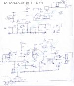
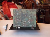
KM Amplifier 10 a dating back from 1977.
See attached files.
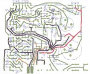
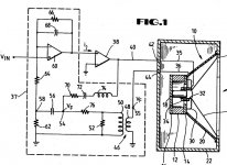
There is a black box receiving power supply and ground. Such black box may thus contain active elements like transistors. There are two input ports on the black box : one receiving an image of the speaker current, and one receiving an image of the speaker voltage. There is one output port on the black box, delivering the feedback voltage.
There is a lamp + LDR combination managing the low frequencies amplitudes. At low frequencies, the LDR has the capability to short circuit a capacitor to ground, hence decreasing the low frequencies amplitudes. Note how the output signal gets lowpass filtered before feeding the lamp : as consequence, such short circuit only happens when there are powerful bass at the the output. This seems to be the protection against excessive speaker excursions.
See attached files.
There is a black box receiving power supply and ground. Such black box may thus contain active elements like transistors. There are two input ports on the black box : one receiving an image of the speaker current, and one receiving an image of the speaker voltage. There is one output port on the black box, delivering the feedback voltage.
There is a lamp + LDR combination managing the low frequencies amplitudes. At low frequencies, the LDR has the capability to short circuit a capacitor to ground, hence decreasing the low frequencies amplitudes. Note how the output signal gets lowpass filtered before feeding the lamp : as consequence, such short circuit only happens when there are powerful bass at the the output. This seems to be the protection against excessive speaker excursions.
Attachments
Last edited:
Hi
The files from msg #42 for example.
i am able to run a few simulations if I remove some steps it seems to enable the convergence of whatever the LTspice is doing but for the file Servo-sound and servo-sound equalized I cannot get a convergence.
If I could get it to work I could share a Matlab routine to do genetic optimization of the parameters (box volume feedback loop filter parameters with target curve etc.).
Mickael
The files from msg #42 do refer to specific components embedded in my custom library named "my_own_npn_pnp_bjt_v402.lib". Surely you have not asked LTspiceIV to use "my_own_npn_pnp_bjt_v402.lib". So, on your side, LTspiceIV doesn't know about the power transistors used. If you are new on LTspiceIV, you better not use the files from msg #42 as they contain a complicated hand-made opamp model using discrete transistors. If you are new on LTspiceIV, you better not use the files from msg #42 as they contain a complicated hand-made power amplifier model using such opamp as front-end plus some discrete transistors you don't find in the LTspiceIV default library.The files from msg #42 for example. I am able to run a few simulations if I remove some steps it seems to enable the convergence of whatever the LTspice is doing but for the file Servo-sound and servo-sound equalized I cannot get a convergence. If I could get it to work I could share a Matlab routine to do genetic optimization of the parameters (box volume feedback loop filter parameters with target curve etc.). Mickael
You better start from msg #60. Over there you have files forming a simpler foundation for what you intend to do. There is no custom library needed. The opamp model and the power amplifier are much simpler. Actually they are the same, basing on a Laplace function definition without any current & voltage limit.
Using the files from msg #60, invest some time in adding the required feedback for implementing a servo-sound arrangement. I can help you if you want.
The files from msg #60 also contain some Monacor speaker models you can use. You may need adjusting the internal loss parameter, depending on how much fiber you put in the box.
Hi,
thanks for the advice but I am not that with LTspice and as I said msg #62:
I have tried to manually edit the net list to include the custom lib by adding .include my_own_npn_pnp_bjt_v402.lib. This gets rid of the MJE15030/1 error but the analysis still runs for ever.
I have included your library in the default library and it gets rid of the Moto error but the analysis is not finishing would you tell me what the analysis is doing I cannot see why the analysis is not converging. Also I was perfectly able to get the MFB Philips model to run.
BTW I am not interested in TS models (I have my own libraries for Matlab and Microcap) but only in closed loop control.
Mickael
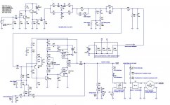
KM amplifier 10 a (simulation v0.1)
see attached files
need to know what's inside the black box
need to put the right R and C values in the input equalizer
see attached files
need to know what's inside the black box
need to put the right R and C values in the input equalizer
Attachments
Last edited:
Wouldn't be complete without Mr. Eraths work.
lweusersgroup : LWE Loudspeakers Users Group
http://groups.yahoo.com/group/lweus...ode=tn&order=ordinal&start=1&count=20&dir=asc
lweusersgroup : LWE Loudspeakers Users Group
http://groups.yahoo.com/group/lweus...ode=tn&order=ordinal&start=1&count=20&dir=asc
Agree !Wouldn't be complete without Mr. Eraths work.
Attachments
I have a few of Mr. Eraths units and I am hoping that one day someone will be able to do the same with a DSP instead of the reactive components and combine it with a good class D amp such as the Hypex nCores...
If you would like one of his units to "disect" please let me know and I can send it to you.
If you would like one of his units to "disect" please let me know and I can send it to you.
A DSP inside the feedback loop would introduce a delay that would impair stability. On the other hand, putting the DSP outside the feedback loop, as preamp, would ruin Mr. Erath's concept as doing so the system would operate like a digital Linkwitz transform.I have a few of Mr. Eraths units and I am hoping that one day someone will be able to do the same with a DSP instead of the reactive components and combine it with a good class D amp such as the Hypex nCores.
Before sending a whole unit, it would be interesting to "virtually regenerate" the four patents filed by Louis W. Erath, using LTspice simulations.If you would like one of his units to "dissect" please let me know and I can send it to you.
1) the US3449518 patent filed 1965 Sept. 15 about current drive, special feedback networks and optical feedback for bass reinforcement at quiet listening levels (did KM ServoSound got some inspiration from this ?)
2) the US3493682 patent filed 1966 Nov. 21 about a new standardized way to connect a loudspeaker to a power amplifier outputting a voltage (the speakers contains the required frequency compensation network, that the amplifier uses in his feedback loop - now tell me what's happening in case of long unbalanced wires ?)
3) the US3497621 patent filed 1967, June 19 about more refined optical feedback circuits for extending the bass boost at quiet listening levels (did KM ServoSound got some more inspiration from this ?)
4) the US5086473 patent filed 1989, Nov. 27 about a feedback system for a subwoofer using current in the feedback path, and a RLC series network also.
After this, we may try "virtually regenerating" a few commercial products sold by Louis W. Erath :
5) the "Model 1" with a normal power amplifier lightly modified for accessing its feedback network
6) the LWE 2A1 Speaker with LWE Amplifier
7) the little "Erath Electronic Suspension" box applied to some standard power amplifier and some standard closed box featuring some Q and Fc.
Viewed from here, the most appealing circuit is the one disclosed in the US5086473 patent filed 1989, Nov. 27.
Being filed in 1989, it comes after thousands and thousands of KM ServoSound systems sold in Europe. Most people will then infer that such patent is worth nothing.
Actually such patent has a high value to my eyes because unlike the KM ServoSound, we find no additional active components. The whole equalization gets done using passive components, and I find this very reassuring, very refreshing compared to the Linkwitz Transform (pre-equalization requiring one opamp), or compared to some complicated feedback requiring opamps, attempting to operate as "velocity feedback" (see JC Bodot "Zippy" in France).
Concerning the US5086473 patent filed 1989, Nov. 27, there is something unclear to me. Is the power amplifier (#38) a conventional power amplifier outputting a voltage, or is it supposed to output a current ? Why is it represented as distinct from the differential input stage (#60) ? Let us read the patent text : "A current signal is delivered to the drive coil (#34) by a broadband audio amplifier (#38)."
Finally one may ask if it is feasible to wire a power amp as Linkwitz transform, for getting a "power Linkwitz transform with voltage gain". Only using resistors and capacitors. No coils, no transformers, no opamps. If this is the case, I'm sorry for Louis W. Erath.
Speaking about JC Bodot in France, that man issued a kind of (biased ?) technical summary about "velocity feedback", before imposing his own "wideband velocity feedback".
One can read it here : http://ddata.over-blog.com/xxxyyy/1/74/30/05/CFP/CineticFeedBack_Ch1_M1.pdf
Unfortunately it is in french.
There is question about bridges used to generate the electronic feedback of the power amplifier, namely the "Voigt bridge", "Maxwell bridge" and "Anderson bridge".
Unfortunately, JC Bodot failed to provide a bibliography and references, so after reading his prose, I still don't know who are Voigt, Maxwell and Anderson, and I still don't know if one of those were the inspiration source for KM ServoSound.
Time to open a few new threads on diyAudio ?
- Louis W. Erath patents and devices, illustrated by LTspice simulations
- towards a "power Linkwitz transform with voltage gain"
- the Voigt bridge, the Maxwell bridge, the Anderson bridge, the KM ServoSound systems, the Louis W. Erath systems confronted to compliance nonlinearities, magnetic nonlinearities, factory dispersion, thermal effects and ageing: are they "speed feedback" systems, or are they equalizers ?
- the JC Bodot "Zippy" in France : is this recycling, improvement, or innovation ?
Attachments
Mr. Erath developed another circuit that worked full range before he died. He made a few units to put in his new Trout powered speakers and made me the only external bi-amp version to use with some Hypex UcD amps. I started the active system but had to put it in storage when I came to Europe for a contract. I hope to pull it out of storage (been a year or so) and get started on it again shortly.
Referring to this one
4) the US5086473 patent filed 1989, Nov. 27 about a feedback system for a subwoofer using current in the feedback path, and a RLC series network also.
I have one home unit and two car units that utilize this circuit. I can offer you one of the car units(uses +/- 15vdc) to play with when you are ready.
The best advice I can give you is to avoid spreading those elements over the world. Try keeping them together, with all cabling, documentation and correspondence in a secure & discrete storage. If there is a cost associated to the secure storage, you'll find people including myself willing to donate money. If some equipments sold by Mr. Erath never had a proper schematic on paper (how possible?), a wiring diagram or a service manual, it is never too late for making them. Let's take an example. If you email me decent pictures from a decent digicam, well in focus, of the PCBs (I mean the fully equipped PCBs), solder side and copper side, plus some other pictures like the power supply wirings and control wirings, I can manually process those pictures, deliver the corresponding schematics, and deliver a simulation using LTspice. Kind of stuff I did with great fun and pleasure with that old KM amplifier 10a (Servo Sound), back in 2008.Mr. Erath developed another circuit ... I hope to pull it out of storage (been a year or so) and get started on it again shortly. Regarding the US5086473 patent filed 1989, Nov. 27 ... I have one home unit and two car units that utilize this circuit. I can offer you one of the car units(uses +/- 15vdc) to play with when you are ready.
Hello steph,Getting rid of the 20mH inductor in the 1:10 immobile voltage synthesis.
See attached picture.
A possibility is to use a ground-referred inductor synthezised by a gyrator. But then, the difficulty is to current feed this ground-referred inductor. I don't want to end up with weird components like OTAs in open-loop or with BJTs in open-loop (aka Nagra tape amplifiers). I need a practical solution based on one or two TL071 or audio-grade opamps.
Another possibility is to 1/p shift the stage. The three resistors become three capacitors. The inductor becomes a resistor. The issues with this approach : loss of DC path for the opamp feedback, small load impedance seen by the opamp at high frequency, possible issue with the capacitor used at the input. Such circuit may operate if adding a serial resistor at the input (say, 100 ohm) and adding a parallel resistor as negative DC feedback (say, 1000k). It could be the TL071 is unable to handle such uncommon arrangement. I'm not sure that faster is better, in such uncommon arrangement, making me doubt about the TL071 (he hates being loaded) and the OPA134 (he is maybe too fast).
Any other idea ?
This difficulty is maybe the reason of the "black box" inside the Servo-Sound. Maybe the Servo-Sound is an accurate bridge feedback with no big concerns about tracking the DC coil resistance (I'm not sure elvee is right in his approach), but with a nice trick (or private joke) for replacing a coil by some organized silicon. In such active box, containing the electronics, a non-copper electronic coil is highly desirable, with no vibration induced distorsion and no risk of detuning. In this context I think that the Servo-Sound "black box" is containing an emitter follower used as poor man's gyrator for implementing the coil, plus a Nagra-inspired (Nagra patented maybe ?) BJT arrangement outputting an AC current (not a voltage) feeding the ground-referred synthezised coil (and associated resistors). Plus an emitter follower, as output buffer.
Is anybody on earth knowing what's inside the Servo-Sound "black box" ?
Thanks in advance,
Steph
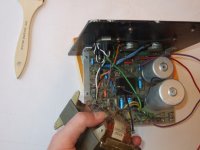
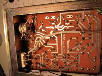
I managed to find out what is in the blackbox of the air preamplifier. The box is made of resin or epoxy. I googled and find out that aceton would deluate the resin or epoxy. Indeed it worked, if you let the blackbox one hour in the aceton, you can scrape off the epoxy. It is a long process but worth doing it. I found 4 resistors, 2 electrolytic capacitors and a 3 piece coil. The aceton made the blue surrounding of the capacitors unreadable. I used a esr/ capacitor meter to find out the cap values.
Hopes this helpes.
I noticed you are from belgium ? Well i am.
Regards,
Peter
Great! What blackbox are we talking about? KM amplifier 10a or KM amplifier 15b?I managed to find out what is in the blackbox of the air preamplifier. The box is made of resin or epoxy. I googled and find out that aceton would deluate the resin or epoxy. Indeed it worked, if you let the blackbox one hour in the aceton, you can scrape off the epoxy. It is a long process but worth doing it. I found 4 resistors, 2 electrolytic capacitors and a 3 piece coil. The aceton made the blue surrounding of the capacitors unreadable. I used a esr/ capacitor meter to find out the cap values.
blackbox
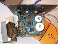
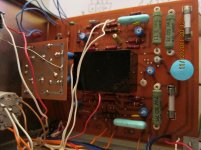
Hello,
I'm talking about the one that is the pre-amplifier ( see attached fotos) BUT my description will help you to find out what is in any blackbox ( servo sound , KM )
Detail : the blackbox is just plastic and is surrounding the epoxy.
If you squeeze the plastic , it comes off, and shows you a brown epoxy box.
Also interesting : on the KM-52 speaker , there is no blackbox on the double-sided pcb !!
Attachments

- Status
- This old topic is closed. If you want to reopen this topic, contact a moderator using the "Report Post" button.
- Home
- Amplifiers
- Solid State
- Servo-Sound made in Belgium