Attached you will find the continuation of posts #30 and #39 about modelling a loudspeaker in fee air, using LTspiceIV.
I have followed bentoronto repeated advice "get a feedback signal and use it" instead of playing with equations and models for trying to synthezise the pure motional voltage.
Bentoronto method provides a very good result, especially when pre-equalizing the signal at the input. Thanks for opening our eyes, bentoronto !
In order this circuit to compute, you need all the subcircuit and symbol files posted on post #39.
P.S. 1
In a real circuit, the two coils located into the pre-equalizer need to be implemented using a gyrator, like we have in analog graphic equalizers.
P.S. 2
If somebody can suggest some spice directives enabling a faster .DC operating point calculation, that would be very welcome. As is, the .AC directive computes in 80 seconds. This is on the slow side when doing fine-tuning.
P.S. 3
I have not calculated nor measured the effective DC coil resistance suppression provided by this circuit. I have no idea if we are close to or above the 80% DC coil resistance suppression quoted in the Werner-Carell experimental work at RCA described in the AES paper dating back from Oct 1957. Later on, I'll try to embed a suppression percentage measurement in the schematic, as design help.
Cheers,
Steph
Attachments
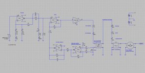
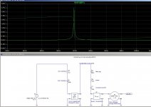
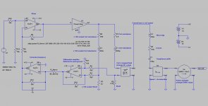
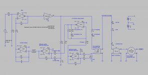
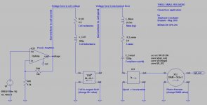
This is almost identical (conceptually) to the circuit I physically made and tested.
The amount of negative resistance can be computed easily: If G is the voltage gain seen from the shunt resistor Rs, then (-R)=(G-1)*Rs
I have convergence problems with your power amp sub, and I had to bypass it.
I deducted from the graphs its gain was about 27.5dB.
This means that (-R)~= (24/2.5-1)*0.33= 2.84 ohm.
This is about 72% of the coil resistance, which is OK without any compensation or precaution.
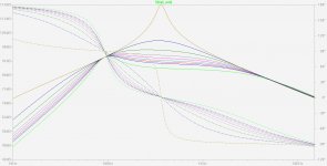
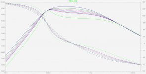
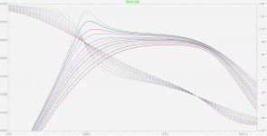
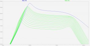
Here you can see the behaviour when changing the value of the feedback resistor from 999k (almost no feedback) to 18k (exagerated feedback).
Note how different the output looks when going from 22k to 18k. Things are getting critical when the feedback resistor is less than 22k.
I don't know what is the optimal feedback resistor value. I would say between 27k and 22k. With such a value, the native 100 Hz resonance doesn't show anymore, and the 100 Hz to 700 Hz response tends to become a symmetric bandpass, something that won't be too difficult to pre-equalize.
Personnaly, empirically, I would use the following rule for determining the optimal practical feedback resistance : in case of a 3% error in the nominal feedback resistor (resistance tolerance, aging, coil DC resistance variation over temperature), I would allow a 2dB variation in the acoustic response.
Anyway, the acoustic response if not yet satisfactory. Pre-equalization is needed.
Obviously, if we use a feedback resistor in the range 27k to 22k, there is a 5th order correction needed :
- 2nd order for raising the amplitude between 40Hz and 100 Hz (steep pass-band boost)
- 2nd order for flattening the amplitude between 100 Hz and 1kHz (damped notch)
- 1st order for getting the 1kHz -> 10kHz response horizontal (kind of high-pass shelving)
This is the pre-correction strategy I've used in the previous post. I think that a 5th order pre-equalization scheme is an acceptable complexity in 2010.
Please note that it may be possible to reduce the complexity of the pre-equalizer, if one has access to the feedback network of the power amplifier. This is the situation we are facing inside a Korn-Macway (aka Servo-Sound) arrangement. I think that we'll still come up with 5th order correction, but splitted between the pre-equalization and the action chain. The overall complexity may thus decrease, like if the pre-equalizer is 3nd order, and the action chain is 2nd order. Need to investigate. Potential stability issues.
Anyway, now that we are playing with current sensing, optimal feedback adjustment and a 5th order equalization scheme, it may be time to see the kind of mechanical complexity and electronic complexity we may face when opting for a dedicated acceleration sensor like used in Philips Motional Feedback systems (MFB) RH541, RH544 and RH545. We shall remember that the accelerometer solution is superior in distorsion reduction, and less sensitive to temperature effects.
We also need to remember that any existing driver may be converted to a Philips MFB arrangement, glueing a small piezo transducer (like used in miniature buzzers) on top of the voice coil, under the dust cap.
For running the simulation files, you need the subcircuits and symbols provided in my previous posts.
Cheers,
Steph
Attachments

Please have a look to the attached pictures.
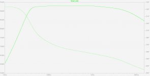
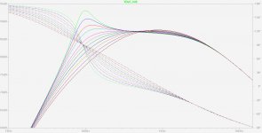
The circuit has not changed. The only change is that we are now zooming on 47k to 27k feedback resistors. The green curve is the one with the 999k resistor (say, no feedback). There you see how it is peaking, without feedback.
The 33k curve is remarkable. I missed it in the previous post. It provides a "straight top" acoustic response, however not horizontal. The "straight-top" feedback strategy may require less pre-equalization efforts :
- 2nd order for raising the amplitude between 40Hz and 100 Hz (steep pass-band boost) (like before)
- 1st order (actually, less than 1st order) for getting the 100 Hz -> 1kHz "straight top" horizontal
- 1st order for getting the 1kHz -> 10kHz response horizontal (kind of high-pass shelving) (like before)
We may thus say good-bye to a gyrator (that's one opamp less) and if there is some access to the feedback network of the power amplifier, the pre-equalizer may only consist on the 40 Hz to 100 Hz steep pass-band boost followed by a simple RC shelving arrangement for getting the "straight top" horizontal.
This being said,
1 - Before making more refined simulations, one must ask ourselves if there will be a tweeter used, and a crossover filter used. What is the effect of the feedback sensing the two currents together (woofer + tweeter) without being able to isolate the woofer current ?
2 - After having answered this, one must ask ourselves if it is a good idea to let the system feed the drivers with a reduced copper resistance, for frequencies above 1 kHz. Knowing that loudspeakers, and tweeters especially, see their sensitivity decreasing because of their coil inductance, I would say that above 1 kHz, we should change the feedback arrangement for increasing the virtual output resistance of the amplifier. Above 1 kHz, the coil inductance is not the sole ennemy. There may also be some short term variations in sensitivity like compression caused by thermal modulation. Driving the transducer using current (forcing a current into it instead of imposing a voltage on it) may add some other benefits, in this area.
For running the simulation files, you need the subcircuits and symbols provided in my previous posts.
It's quite funny, reinventing Thiele-Small and the amplifier-to-speaker interface ! Hope you enjoy like me.
With points 1 and 2 coming at the table now, we are not yet finished !
Cheers,
Steph
Attachments
I never realized you could have so much fun with numbers. I guess there may be some future to this modeling stuff (kidding... but my respect for Steph's deft handling of the simulation is sincere).
The question of choice of sensor is very important. For a long time, my impression has been that for small excursions, a quality driver's motor is pretty linear. Moreover, some of those non-linearities are zero'd away when used as feedback backwards, if you know what I mean.
In contrast to some cheap accelerometer glued to a paper dustcap.
Are cheap accelerometers really as linear as the motor in a good driver?
I certainly do.It's quite funny, reinventing Thiele-Small and the amplifier-to-speaker interface ! Hope you enjoy like me.
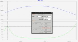
Before proceeding, I think the numerical values of the speaker's parameters should be refined: I plotted the simulated speaker's impedance, and the resonance is obviously too sharp. It is probably necessary to increase the value of R2 in your model, but I don't have the expertise to give meaningful advice on this point.
If the data of an actual speaker could be found, it would be a good starting point.
Please, don't see my remark as a criticism, I think you do a fantastic job.
Attachments
hi bentoronto,
I guess we need a more elaborate feedback, still using the voice coil and no other sensor, for getting rid of the 5th order or 4th order pre-equalizer. What we want now is a feedback arrangement allowing us to get a flat horizontal acoustic response from 35 Hz to 8 kHz. What if we now introduce the concept of the feedback bridge for extracting the coil back EMF and use it as feedback ? Would it suit you now ? Or, are there important things we missed regarding the "pure negative resistance drive" approach ?
Cheers,
Steph
I did it on purpose for pedagogic reasons. If you look to the compliance value, you'll also see that it is more representative of a closed box system, than a free air system where resonance is less pronounced. I wanted to see a clear contrast between open-loop and servo-driven. Starting with such parameters also makes quite obvious that we need a strong extension below 100 Hz. All in all, this "worst case" initial choice gives us some headroom : if we succeed with such data, then certainly we'll succeed with all possible drivers.I think the numerical values of the speaker's parameters should be refined: I plotted the simulated speaker's impedance, and the resonance is obviously too sharp.
What kind of driver would you advise, that is well documented, decent, not expensive and available both in Europe, Canada and USA ? Here in Europe we have Visaton and Monacor as main affordable suppliers. What's the choice in Canada and in USA ? Okay for selecting one European driver and one USA driver, and making all the simulations with them starting from now.
Steph
Last edited:
Here is a brief bridge feedback description, as simple as possible. The idea is to create a feedback signal that's more elaborate than just the current in the coil. The aim is to get a more useable acoustic response than the one we've got using the negative resistance drive arrangement. No more potato-shaped acoustic responses, and no more declining trend in the medium range, those are the objectives now.
1. The expedite bridge feedback
The voltage available at the shunt gets compared with another voltage created by an extra branch. That other branch is a static x 100 scaled copy of the immobile loudspeaker impedance. The 3.9 ohm copper of the coil becomes 390 ohm. The 200 microhenry coil inductance becomes 20 millihenry. The 0.33 ohm shunt becomes 33 ohm. In this x 100 scaled branch, there is of course no back EMF developing. That's the very important point.
The branch current, over there, is thus maximum, always more than 1/100 of the real loudspeaker current. The current is always more because in the x 100 scaled branch, there is no back EMF decreasing the overall voltage. Let's call this current the immobile speaker current.
An inexpensive way to extract something close to the back EMF is to compute the potential difference developing on each shunt. If the back EMF is considerable, like at speaker resonance, the real current and the immobile currents will be considerably different, and a considerable potential difference will exist between the two shunts. Such approach has the advantage of simplicity. Let us call this approach the expedite bridge feedback arrangement.
2. The accurate bridge feedback
How would you extract the back EMF, in a perfectly accurate manner ? There are not thousand different ways. Say there is a 0.33 ohm shunt measuring the current in the loudspeaker. There is thus a voltage developing, proportional to the coil current. Let us now multiply this current by the DC coil resistance plus the coil inductance. In a scaled manner. Like 1/1000th of the current in x100 impedances. Then we get an accurate image of the immobile voltage inside the loudspeaker. We know that the total voltage on the loudspeaker is the sum of the immobile voltage plus the back EMF. A simple difference amplifier can thus do the job, working on a 1/10 scaled down voltage. The difference amplifier delivers a voltage equal to 1/10th of the back EMF.
3. Driving at constant coil speed - the consequences
Anyway, being the expedite way or the accurate way, we realize that the loudspeaker current is still used as positive feedback (like in the negative resistance drive), but in a more elaborate way. This enables us to say that the bridge feedback approach is a negative resistance drive with more concern about the linearity of the acoustic response, because this time, we force the amplifier to drive the loudspeaker at constant back EMF.
But wait a minute ?
Isn't there an issue ?
In the bass range, with massive bridge feedback applied, we will drive the loudspeaker at constant back EMF. However, back EMF is proportional to the coil speed inside the loudspeaker. If you operate a loudspeaker at constant coil speed, knowing that constant SPL is constant coil acceleration, what kind of acoustic response will we get ?
Constant coil acceleration, determining a flat acoustic respoonse, is the derivative of constant coil speed. So, if you drive at constant coil speed, the acceleration (determining the acoustic response) is a 1st order increase with frequency.
We need to realize this before putting bridge feedback in action. Otherwise we'll get troubled by the results. In the bass range, the more we apply bridge feedback, the more the bass response will show as 1st order highpass ! The bridge feedback is thus eating the bass response.
Actually, this is a great feature because pre-equalization will simplify a lot. A 1st order bass boost may suffice, in theory, as pre-equalizer. The more bridge feedback we apply, the simpler the pre-equalizer may get, simplifying down to a 1st bass boost arrangement.
Cheers,
Steph
Some files about the expedite bridge feedback.
It looks encouraging. The more we apply expedite bridge feedback, the more we get a 1st-order high pass in the bass. This is exactly as expected. On the other hand, the more expedite bridge feedback we apply, the more the 1kHz range gets lifted, by 2 or 3 dB. We still face a potato-shaped acoustic response, however, this time the top is horizontal.
The easy to pre-equalize bass response and the horizontal top shape are two improvements compared to the negative resistance drive approach.
See the attached pictures and attached files.
For running the simulation files, you need the subcircuits and symbols provided in my previous posts.
Cheers,
Steph
Attachments
Steph, Thank you for re-awakening my interest in this technique. For me the interest was in varying the negative resistance generated by the amplifier so that some of the voice coil resistance was cancelled out.
Thus the effective Qes was changed and hence Qts. So you could match a drive unit to a particular smaller cabinet. Even today you can get drivers which are otherwise good but have too high a Qts to give a reasonable cabinet size.
830657 - Peerless SDS-164-THP 6.5" woofer coated paper - Europe Audio
Using this technique you can vary the Qts to give a reasonable small size.
With some speakers you seem to need to apply a lot of power before the bass starts to work. With this technique the bass starts working at low levels!
It is well worth continuing your research.
Some files about the accurate bridge feedback.
It looks pretty decent. The more we apply accurate bridge feedback, the more we get a 1st-order high pass in the bass. This is exactly as expected.
On top of this, the accurate bridge feedback effect extend to 1 kHz, where the gain reduction is still 3dB approx. Can we thus say that even at 1 kHz, the acoustic response is servo-controlled ? I have a thin doubt.
There are no side-effects like getting a potato-shaped or sloped acoustic response curve when applying more accurate bridge feedback. The only drawback is a slight amplification of the high frequency decreasing slope, above 4 kHz.
For R_Servo, a value between 5.6k and 8.2k seems optimum. We then get a wideband flat top. Does this range coincide with the most resembling 1st order high-pass acoustic response in the deep bass ? If yes, it helps simplifying the pre-equalizer, a simple 1st-order bass boost.
The above features make the accurate bridge feedback a very attractive technique. On paper.
Let us take some time comparing those promising results, with the Philips MFB system relying on a piezo acceleration sensor fitted inside the dust cap.
A Philips MFB system can't manage the feedback at frequencies higher than 500 Hz, where you enter the uncertain region of the piezo disc mechanical resonance.
Another disadvantage of the Philips MFB is that you introduce a "device into the device", governing the device, having its own sonic signature.
This reinforces the idea that a Philips MFB needs to be confined inside a narrow frequency band, say between 20 Hz and 120 Hz, where most of the sound textures are not yet audible.
On the other side, a Philips MFB system can battle against suspension and magnetic field non-linearities at high membrane excursions. That's a great feature. Fortunately, this is totally compatible with the above conclusion about needing to confine the piezo-based MFB inside the deep bass range.
At this stage, my conclusions are :
1 - The accurate bridge feedback seems attractive and easy to pre-equalize.
2 - The piezo-based MFB is still a valid option if confined inside the 20 Hz to 120 Hz frequency band, where excursion matters.
3 - With adequate feedback applied, the accurate bridge feedback seems to govern the acoustic response up to 1 kHz. This is to verify. Especially with temperature drifts and other errors caused by physical components.
4 - Anyway, the high frequency extension of the accurate bridge feedback needs to be put in competition with an other way to drive a speaker at high frequency, like using a constant current drive for overcoming the inductance above 1 kHz.
5 - I have not yet investigated potential stability issues, submitting some key components to drift, thermal and aging effects.
6 - Last but not least I have not yet simulated a Philips MFB system using a piezo accelerator, and I have no idea how to blend the control, depending on the frequency, allocating MFB from 20 Hz to 120 Hz, allocating the accurate bridge feedback from 120 Hz to 1 Khz, and current-driving the transducer above 1 kHz.
7 - If there is a passive crossover filter somewhere, I don't know how to handle it, in the context of such 3-in-1 amplifier-speaker interface (MFB piezo, bridge feedback, current drive).
Do we know such 3-in-1 speaker interface yet ? Any practical realization ? Will we see, one day, loudspeakers equipped with a digital bus, telling the amplifier how it needs to configure the analog drive circuitry and feedback ? This could be the future of analog audio amplifiers. You can't tailor the feedback arrangement of class D amplifiers so easily. For the moment.
See the attached pictures and attached files.
For running the simulation files, you need the subcircuits and symbols provided in my previous posts.
Cheers,
Steph
Attachments
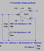
Getting rid of the 20mH inductor in the 1:10 immobile voltage synthesis.
See attached picture.
A possibility is to use a ground-referred inductor synthezised by a gyrator. But then, the difficulty is to current feed this ground-referred inductor. I don't want to end up with weird components like OTAs in open-loop or with BJTs in open-loop (aka Nagra tape amplifiers). I need a practical solution based on one or two TL071 or audio-grade opamps.
Another possibility is to 1/p shift the stage. The three resistors become three capacitors. The inductor becomes a resistor. The issues with this approach : loss of DC path for the opamp feedback, small load impedance seen by the opamp at high frequency, possible issue with the capacitor used at the input. Such circuit may operate if adding a serial resistor at the input (say, 100 ohm) and adding a parallel resistor as negative DC feedback (say, 1000k). It could be the TL071 is unable to handle such uncommon arrangement. I'm not sure that faster is better, in such uncommon arrangement, making me doubt about the TL071 (he hates being loaded) and the OPA134 (he is maybe too fast).
Any other idea ?
This difficulty is maybe the reason of the "black box" inside the Servo-Sound. Maybe the Servo-Sound is an accurate bridge feedback with no big concerns about tracking the DC coil resistance (I'm not sure elvee is right in his approach), but with a nice trick (or private joke) for replacing a coil by some organized silicon. In such active box, containing the electronics, a non-copper electronic coil is highly desirable, with no vibration induced distorsion and no risk of detuning. In this context I think that the Servo-Sound "black box" is containing an emitter follower used as poor man's gyrator for implementing the coil, plus a Nagra-inspired (Nagra patented maybe ?) BJT arrangement outputting an AC current (not a voltage) feeding the ground-referred synthezised coil (and associated resistors). Plus an emitter follower, as output buffer.
Is anybody on earth knowing what's inside the Servo-Sound "black box" ?
Thanks in advance,
Steph
Attachments
Last edited:
This discussion has long-since passed well beyond my modest understanding of models or amps. But I have a few thoughts to toss in anyway.
Talking of 35 to 8 kHz is far higher or broader than any single driver can handle. Worse I think, once you get up into a range where voice coil inductance is large, you will be unable to control the feedback loop phase. Same is true of an accelerometer feedback and inconceivable with acoustic phasing.
Back to the simple notion of grabbing some feedback. What are the advantages of perfect mirroring? By not accounting for inductance or resistance changes with temperature, your feedback is ever so slightly changed and hence drive power to the speaker. But that is far different in scale and aural consequences from harmonic distortion, for example.
The major corrections have to do with the relation of drive power (or voltage or current) and audible output. You need to address that. The classic driver is really a tricky compromise of motor and mass and cone break-up leading to a kind of flat output in ordinary enclosures. With MF, you are entirely ignoring that compromise and driving the driver as you (the man with the feedback in his hands) cares to drive it, not as the artist who created the driver for a low output impedance (super high damping factor) amp.
A driver needs an evolved motor that has all the little tricks to stay linear (like very long or very short voice coil, etc). Virtually nothing can pump serious volumes of air at 35 or below except a horn or maybe a large driver with an enormous peak-to-peak excursion. I never consider resonant boxes to be in the audiophile realm.
Speaking of enclosures, only a sealed box or infinite baffle has a simple relation between driver excursion and sound output. Maybe also a Klipschorn, although the low-end output is full of bumps, because it has a small sealed box behind the driver and has worked nicely for me with MF (of course, I did blow up one genuine Klipsch driver one very sad day fooling with MF).
I've made changes to my system recently. The only MF I am now using with the woofer (Klipschorn) is based on long leads to the speaker and a Kenwood Basic M1 Amp with "Sigma Drive." This amp is clearly grabbing some motional feedback although not necessarily smoothing the response curve. As per my earlier comment, there are bigger advantages to gain with MF than just a smooth frequency curve.
Ben
Last edited:
Not sure ... The 3-in-1 amplifier to driver interface may provide this. At low power, say up to 25 watts using a d'Appolito arrangement consisting on two 10cm drivers, or two 13 cm drivers. Plus a 20mm neodyme tweeter inbetween.Talking of 35 to 8 kHz is far higher or broader than any single driver can handle.
MFB 35Hz to 120Hz (Motional Feedback)
ABF 120Hz to 1 kHz (Accurate Bridge Feedback)
CDC 1 kHz to 8 kHz (Current Driven Coil)
Using MFB below 120 Hz, you linearize the whole speaker, even at large excursion, but you don't allow the piezo transducer to impose his tonal signature where sound texture matters.
Using ABF between 120 Hz to 1 kHz, you drive the speaker without approximations, basing on his tonal signature, and nothing else, and nothing more. If the driver magnetics are ill, you'll get an ill sound. If the driver magnetics behave like a giant microphone, you'll get an ultra-fi sound.
Using CDC above 1 kHz, you don't see the effect of the coil inductance anymore. You don't face coil inductance nonlinearity anymore. You force a current inside the coil. If the speaker was ill-designed like cone break-up overcompensating the high frequency roll-off caused by the inductance, you'll see it more accurately. I agree. You'll have the choice between electronically equalizing the amplifier frequency response, or selecting a more honest driver. How are you going to blend the main driver with the tweeter, if the acoustic response of the main driver gets fuzzy (uncontrolled cone break up) between 4 kHz and 8 kHz ?
Steph
Is your black box active, ie does it need a power supply? Did you reverse engineer the circuitry immediately adjacent to it?This difficulty is maybe the reason of the "black box" inside the Servo-Sound. Maybe the Servo-Sound is an accurate bridge feedback with no big concerns about tracking the DC coil resistance (I'm not sure elvee is right in his approach), but with a nice trick (or private joke) for replacing a coil by some organized silicon. In such active box, containing the electronics, a non-copper electronic coil is highly desirable, with no vibration induced distorsion and no risk of detuning. In this context I think that the Servo-Sound "black box" is containing an emitter follower used as poor man's gyrator for implementing the coil, plus a Nagra-inspired (Nagra patented maybe ?) BJT arrangement outputting an AC current (not a voltage) feeding the ground-referred synthezised coil (and associated resistors). Plus an emitter follower, as output buffer.
Is anybody on earth knowing what's inside the Servo-Sound "black box" ?
Thanks in advance,
Steph
Did you try to apply a stimulus current to have an idea of its characteristic?
Considering the overall technological level of the system it is included in, I doubt it is little more than some special shunt, or current transformer, or mixture of both.
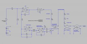
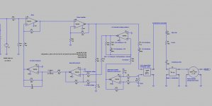
The following arrangement is different from the previous ones. Of course, it is still based on the coil back EMF. The aim is to use the coil back EMF feedback between 100 Hz to 1 kHz. One decade is quite wideband in loudspeaker technology.
We don't care about peaking in the bass. We don't care about the deep bass rendering. Those frequencies below 100 Hz may be governed by a Philips MFB scheme (the one with a piezo accelerometer), in a better way, reducing the distorsion that may come from the suspension and magnetics non-linearities, when the membrane excursion is large.
What we want here, with the wideband coil back EMF feedback scheme, is to knock down the acoustic response by 12 dB between 100 Hz and 1 kHz, using the coil as velocity sensor. This way, we can expect a 4 times more precise rendering of the musical message between 100 Hz to 1 Khz.
This wideband coil back EMF feedback is thus complementary with the Philips MFB arrangement.
How to practically combine a coil back EMF feedback (velocity sensor) with a piezo feedback (acceleration sensor) ?
There is some info available about the Philips MFB here :
http://www.diyaudio.com/forums/solid-state/166061-philips-motional-feedback-mfb.html#post2177780
Cheers,
Steph
Attachments
Here is an example of circuit combining a coil back EMF feedback (velocity sensor) with a piezo feedback (acceleration sensor) :
http://www.diyaudio.com/forums/solid-state/166449-avfb-loudspeaker.html#post2178299
http://www.diyaudio.com/forums/solid-state/166449-avfb-loudspeaker.html#post2178299
I went to Elak (an electronic shop in Brussels) grabbing some info about loudspeaker drivers one may eventually purchase at decent prices here in Europe. They gave me the 2009 MONACOR catalog, no less than 710 pages. I did an arbitrary selection of drivers :Before proceeding, I think the numerical values of the speaker's parameters should be refined: I plotted the simulated speaker's impedance, and the resonance is obviously too sharp. It is probably necessary to increase the value of R2 in your model, but I don't have the expertise to give meaningful advice on this point. If the data of an actual speaker could be found, it would be a good starting point.
Celestion Truvox 1225 ... 500 Watt thay say, but excursion is only +/- 2.4 mm. A joke ? Not suited to deep bass where excursion matters ?
Monacor SPH-100/8 ..... inexpensive, wideband, +/- 3.5 mm excursion
Monacor SPH-100C ...... looks hi-tech but beware the nasty resonance at 9.0 kHz
Monacor SPH-135C ...... looks hi-tech but beware the nasty resonance at 6.5 kHz
Monacor SPH-165 ......... inexpensive, wideband, +/- 3.5 mm excursion
Monacor SPH-165CP ..... looks high-tech but beware the nasty resonance at 7.0 kHz
Monacor SPH-170 ........ inexpensive, wideband, +/- 3.0 mm excursion
Monacor SPH-170C ...... looks hi-tech, wideband, manageable controlled resonance at 4.5 kHz, +/- 4.0 mm excursion
Monacor SPH-176 ........ wideband, +/- 5.5 mm excursion
Monacor SPH-210 ........ nice traditional driver, no pronouced high frequency resonance, +/- 3.5 mm excursion
Monacor SPH-225C ...... looks high-tech, wideband, manageable controlled resonance at 3.0 kHz, +/- 6.0 mm excursion !
Monacor SPH-255 ....... traditional driver, not to be used above 2 kHz, +/- 4.5 mm excursion
Monacor SPH-275C ...... looks high-tech, wideband, small manageable controlled resonances at 3 kHz, +/- 6.0 mm excursion !
Monacor SPH-315 ....... traditional driver, not to be used above 2 kHz, +/- 4.5 mm excursion
The MONACOR catalog provides the impedance curve along with most electrical, mechanical and electromechanical data in tabular form. Looks nice at first glance.
I was thus able to enter the necessary data in the LTspiceIV Thiel-Small toolbox. See here : http://www.diyaudio.com/forums/solid-state/166467-thiele-small-reloaded-ltspiceiv.html#post2179287
I must however report a few facts.
1.
The equivalent loss resistor is never quoted by Monacor. However, it is easy to retrieve it when looking at the impedance plot. When all the other parameters have been duly entered in the LTspiveIV toolbox, an impedance plot (voltage / current) tells you if you need to increase or reduce the equivalent loss resistor. The maximum impedance at resonance is governed by the value of the equivalent loss resistor. I have thus set the equivalent loss resistor for obtaining the same max value, under LTspiceIV toolbox, than showed by the impedance plot published by Monacor.
2.
The coil inductance specified by Monacor seems to be systematically exagerated. The coil inductance specified in the Monacor tables doesn't fit with the value showing on the Monacor impedance plot at 20 kHz. So, as expected, if one enters the tabular value of the coil inductance in the LTspiceIV toolbox, the impedance displayed by LTspiceIV at 20 kHz is ways above the impedance showed in the Monacor impedance plot at 20 kHz. In order to get a impedance at 20 Khz equal to the value displayed by the Monacor impedance plot, I have adjusted (lowered) the value of the coil inductance in the LTspiceIV models. This needs to be investigated. The value of the coil inductance is of importance in the Servo-Sound applications (back EMF voltage extraction).
3.
After having entered all the data in all the models, we can't say that there is always a perfect match between the free-air resonance frequency, comparing the Monacor impedance plot with the Monacor tabular data, and with the LTspicsIV impedance plot.
Let us take an example : the SPH-225C (quite my favourite driver, from the supplied data) has the resonance peak at 46 Hz on the graph that is supplied by Monacor. But when you read the Monacor tabular data, they say that the resonance is at 39 Hz. And when you ask LTspiceIV, the impedance peak occurs at 39.9 Hz.
We have the same case with the SPH-210 (a traditional regular driver). It has the resonance peak at 34 Hz on the graph that is supplied by Monacor. But when you read the Monacor tabular data, they say that the resonance is at 28 Hz. And when you ask LTspiceIV, the impedance peak occurs at 27.8 Hz.
So what ?
Would be nice if somebody takes some time explaining me why the inductance values (tabular data) specified by Monacor are always incompatible with the Monacor impedance plots, and why the Monacor resonance frequency value (tabular data) are incompatible with the Monacor impedance plots.
On top of that, if would be nice if somebody takes some time explaining me big differences we see in the value of the equivalent loss resistance, for a given diameter. The SPH-165CP as an equivalent loss resistance equal to 0.47 ohm, while the SPH-165 has an equivalent loss resistance equal to 1.15 ohm. That's a ratio of 2.45 for the same loudspeaker diameter. Where are those losses located ? Spyder material ? Suspension material ?
Then, last but not least, beyond 2 kHz, there is always a huge difference between the frequency response plot provided by LTspiceIV (which is a smooth 1st order low pass) and the measured frequency response published by Monacor (which is quite horizontal until 4 kHz, and quite erratic above). Am I right in saying that no loudspeaker larger than 10 cm diameter is capable of working like a piston above 2 kHz ? It seems that there is a kind of dark alchemy, between 2 kHz and 4 kHz, with the theoric frequency response being already a lowpass 1st order, contrasting with most real loudspeaker drivers still maintaining a horizontal frequency curve between 2 kHz and 4 kHz. Surely there is a kind of diffuse resonance taking place, exploited by the designers. Is this a healthy, valid strategy when it is so easy nowadays to electronically equalize a driver ? And then, above 4 kHz, when the diffuse resonance ends, we get something quite erratic in the most common, less carefully designed drivers, something completely erratic like multiple, sharp resonance peaks. How can we hope music coming out of something like this ? How do we have a chance blending a tweeter in phase above 4 kHz ?
I'm really asking myself, now, if it is worth trying to simulate a loudspeaker above 2 kHz, using LTspiceIV, realizing all the "tricks" that may be applied by the loudspeaker drivers designers and engineers, mainly a diffuse resonance between 2 kHz and 4 kHz, and a potentially, a totally erratic membrane behaviour above 4 kHz, that gets more or less invisible when plotting the curves under certain modalities like a fast analog frequency sweep with a slow integrating time constant.
Why don't they publish the FFT plot, along with the FFT phase curve ? The FFT phase curve immediately tells you if your system is actually breaking-up in a dozen of individual subsystems, starting from a given frequency.
I have the impression that some said-to-be hi-tech drivers like SPH-100C, SPH-135C, SPH-165CP are actually suffering from a sharp membrane break-up above 5 kHz, without damping. I guess those drivers require an energic low-pass filters, or possibly, an energic and expensive RLC tuned filter, eating the main breakup frequency. That's good for those ones selling filtering coils and filtering capacitors. Oops, did I mention Monacor was also selling filtering coils and filtering capacitors ?
I have not selected any aluminium-cone driver (SPH-100AL and SPH-130AL), for the exact same reasons. Their behaviour is catastrophic above 8 kHz. You need an energic and expensive RLC tuned filter, for avoiding the driver batteling with the tweeter.
You may ask why I have not included the SPH-130 on my preferred list. Looking at the frequency response plot published by Monacor, this driver exhibits a perfectly linear frequency curve until 7 kHz, then a smooth decrease leaving a perfect place for a tweeter. Unfortunately, this driver only provides a linear excursion of +/- 2 mm. He can't take deep bass. He needs to be used as midrange. And, if you want to get a nice midrange, you are always better with two well damped kevlars, 10 cm diameter, in a d'Appolito configuration (tweeter inbetween). Must say I don't understand why Monacor specifies the xmax at +/-2 mm for this driver, because the suspension is a high-excusrion type. So, surely, the limitation is in the coil height, or magnetic circuit height. Or, simply, the data is wrong, maybe he can deliver the standard +/- 3.5 mm excursion ?
Is there a Monacor well damped kevlar, 10 cm diameter, to be used as midrange ? I don't think so. The SPH-102KEP looks suspicious (positive slope above 1 kHz - hard to filter), the SPH-135KEK looks fine but it is a 135mm diameter, quite expensive (you need 4 in a stereo d'Appolito), and surely with a 135 mm membrane, there is a problem in the polar diagram above 4 kHz. As said above, the SPH-100C (carbon fiber cone) is under-damped above 7 kHz, making it difficult to filter. The SP-100AL has a crazy response curve above 6 kHz making it difficult to filter. Plus the fact that it is expensive.
Actually, a nice medium driver would be the MSH-116/4. The response curve is remarkably flat from 250 Hz to 10 kHz. This would be my choice, regarding a medium driver. It provides a +/- 1mm excursion. This excursion is however not not compatible with a subwoofer. If this medium driver gets used with a subwoofer, he will be asked to reproduce 120 Hz at a fairly high level, with a required excursion in the order of +/- 2.5 mm when listening loud in a living room.
So what would be the preferred medium driver, above a subwoofer, requested to deliver 120 Hz ? My preferred solution is to take a pair of Monacor CRB-100CP (they have a carbon fibre membrane) in a d'Applolito arrangement, take some time dismantling their coax tweeter, take some time increasing the membrane damping using semi-flexible varnish - "huile de lin" in french - with some additives, and take some time installing a damped centre piece - "ogive" in french - at the place previously occupied by the tweeter. Then you get an excellent diyMedium driver able to cover 120 Hz to 7 kHz with a wide polar diagram.
For more power, use the CRB-130CP, and if you want to have fun with some vintages, use the same trick with the oval CRB-915CP. It is amazing to realize what can be achieved, when doing some finishing on inexpensive mass-produced items.
Now about the coax tweeters that just got dismantled. Put them in the bin, as they don't behave decent above 13 kHz, and on top of that they have a very short thermal time constant.
If a short thermal time constant is not an issue for you, you may use some quality neodyme tweeters, miniature. The first good ones went on the market about 10 years ago : CP13 from Visaton. They are very good if set at 6 kHz, 1st order high pass (one capacitor) and time-delay compensated (using mechanic offset or using electronic delay). They are very small (13 mm in diameter), and that's good for getting the d'Appolito units as close as possible.
In the Monacor 2009 catalog, I can see some recent neodyme tweeters, I should test, for comparing them to the CP13 Visaton. With a 28 mm diameter silk dome, they are all bigger than the CP13 Visaton. I don't know if they sound as good as the CP13 Visaton, I don't know if they may be filtered at a lower frequency than 6 kHz (that's what the CP13 Visaton demand), and I don't know if their polar diagram is as good as CP13 Visaton. They are Monacor DT-284 and DT-25N.
I just bought a full duplex USB sound card with line-in and line-out, and a AudioTester3 licence here : audioTester
And just in case, I still have the good old SpectraLab 4.32 from : STonline
So it could be that next month, I'll be again measuring and tweaking loudspeakers drivers like I used to do 10 years ago.
Steph
Attachments
- Status
- This old topic is closed. If you want to reopen this topic, contact a moderator using the "Report Post" button.
- Home
- Amplifiers
- Solid State
- Servo-Sound made in Belgium