Or, in the speak of textbooks, "shunt sampled" feedback. Woo boy, we're dangerously close to needing an electrical engineering degree to stay in the boiler room.
Antoinel,
In today's terms, Schade feedback is called "Parallel Voltage Feedback" (PVF), and is not uncommon. Check out Nelson's Zen amp for a clear example of how it is used with semiconductor amplifiers.
The application of PVF reduces distortion caused by gain changes that result from changes in the load being driven. However, my simulation tests indicate that the difference in distortion between a MOSFET with and without PVF is negligible when the device is driving no load, other than RD.
The distortion-reducing (actually output resistance reducing) mechanism of PVF is quite simple;
1) The SS device output current becomes partially dependent on the output voltage due to the application of PVF.
2) Vin and PVF are average-summed at the input of the device which lowers the device's mu and gm.
3) If Vout is reduced by loading and not by a change in Vin, then this results in a proportionate increase in Vin (due to PVF), and the correct level of Vout is re-established, essentially mimicking a device with lower inherent Ro.
My simple view of Schade Feedback
Schade presented five requirements for an ideal power vacuum tube. They are shown on page 323 in his publication which was entitled "Beam Power Tubes", and provided to us by Zen Mod in a previous post. The 5th requirement of this set is the one most relevant to the subject of feedback. It was : Effective damping of resonant loads. The resonant load is the woofer with specific focus on its impedance below ~100 Hz.
The first 40 pages of Schade's paper articulated the structure-function -performance of triodes, tetrodes and pentodes [tubes] which culminated in the development of his Beam Power Tube [BPT]. BPT was still deficient in its effective damping of resonant loads. He wrote on page 328 this important statement: "It will be shown later that the characteristic [aka requirement #5] of such a tube can be changed into that of a very good low-impedance triode by the use of an inexpensive circuit"
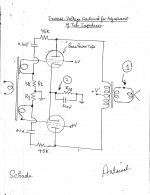
This takes us to the attached schematic which Schade entitled "Circuit with Inverse Voltage for Adjustment of Tube Impedance. It is important to note the objective of Negative Feedback a la Schade which was to lower the internal impedance of BPT so a to derive the benefit or to get the outcome which fulfilled requirement #5.
Schade concluded from his schematic that inverse voltage feedback emanating from nodes #1 [secondary of output transformer], and #2 which is the un-bypassed self-biasing resistor [common cathode] do not reduce the effective plate impedance of BPT; otherwise he would have declared loud an clear.
Inverse or negative voltage feedback from the high impedance node of the tube's plate to its grid via the series 45K and 0.1 uf [10%} met as close as possible the requirement #5.
In a past post, Dr. Mazzola used F2 and F2J to exemplify the use of Schade feedback therein. Now, it is simple to transfer the objective and outcome of Schade feedback for BPT to any transistor.
Best regards
.
Schade presented five requirements for an ideal power vacuum tube. They are shown on page 323 in his publication which was entitled "Beam Power Tubes", and provided to us by Zen Mod in a previous post. The 5th requirement of this set is the one most relevant to the subject of feedback. It was : Effective damping of resonant loads. The resonant load is the woofer with specific focus on its impedance below ~100 Hz.
The first 40 pages of Schade's paper articulated the structure-function -performance of triodes, tetrodes and pentodes [tubes] which culminated in the development of his Beam Power Tube [BPT]. BPT was still deficient in its effective damping of resonant loads. He wrote on page 328 this important statement: "It will be shown later that the characteristic [aka requirement #5] of such a tube can be changed into that of a very good low-impedance triode by the use of an inexpensive circuit"
This takes us to the attached schematic which Schade entitled "Circuit with Inverse Voltage for Adjustment of Tube Impedance. It is important to note the objective of Negative Feedback a la Schade which was to lower the internal impedance of BPT so a to derive the benefit or to get the outcome which fulfilled requirement #5.
Schade concluded from his schematic that inverse voltage feedback emanating from nodes #1 [secondary of output transformer], and #2 which is the un-bypassed self-biasing resistor [common cathode] do not reduce the effective plate impedance of BPT; otherwise he would have declared loud an clear.
Inverse or negative voltage feedback from the high impedance node of the tube's plate to its grid via the series 45K and 0.1 uf [10%} met as close as possible the requirement #5.
In a past post, Dr. Mazzola used F2 and F2J to exemplify the use of Schade feedback therein. Now, it is simple to transfer the objective and outcome of Schade feedback for BPT to any transistor.
Best regards
.
Attachments
During the period of 1975-1979, I was at the Champaign/Urbana campus of the University of Illinois; which was the birthplace of the Parachuting Streakers. I remember on a bright sunny day a chance encounter with possibly Mr. Pass in its auditorium for concerts; demo'ing with other competitors powerful amps driving loudspeakers with low frequencies which caused me to literally run away from their intense sound pressure. This concert auditorium hosted The Carpenters, Tom Jones and Elvis [his final performance] in addition to others which I attended. Those were the days.
I have visited there once during those years, but not on that occasion....

In today's terms, Schade feedback is called "Parallel Voltage Feedback" (PVF), and is not uncommon.
By deference to Horowitz and Hill, I have referred to it as "shunt feedback",
although you can imagine a difference, as their example was that of the
classic inverting op amp. Parallel Voltage Feedback seems like a reasonably
apt phrase although "Schade" allows for reference to Schadenfreud.
I have visited there once during those years, but not on that occasion....
My recollection of your show'n tell of equipment is way after the phenomenon of streaking died off.

Pop Quiz!
Google search of Schade Feedback gave several references; including the parent paper by Schade. This topic showed up in the Tubes forum of diyaudio. Interesting schematics and discussions therein.
Failed to mention in my previous post that the Ideal Power Tube according to Schade has low distortion; which is requirement #1 out of the 5. His inverse voltage feedback lowered the distortion of his proto power amp.
Quiz: Do diyF6, diyF5, and diyCSX1 incorporate a blatant or a subtle or no Schade Feedback?
By deference to Horowitz and Hill, I have referred to it as "shunt feedback",
although you can imagine a difference, as their example was that of the
classic inverting op amp. Parallel Voltage Feedback seems like a reasonably
apt phrase although "Schade" allows for reference to Schadenfreud.
Schadenfreude indeed,
You engineering gurus do derive pleasure by confounding us mere mortals.
It's not just "mere" mortals. Engineering gurus often confound engineering gurus.
On a serious note, it looks like there is a lot of interest here on the subject of negative feedback. Cool.
On a serious note, it looks like there is a lot of interest here on the subject of negative feedback. Cool.
Schadenfreude indeed,
You engineering gurus do derive pleasure by confounding us mere mortals.
Schadenfreude indeed,
You engineering gurus do derive pleasure by confounding us mere mortals.
On the contrary. My deepest satisfaction is to share what I have learned.
On the contrary. My deepest satisfaction is to share what I have learned.
My deepest satisfaction would be to understand what you've shared
What... "Schade" allows for reference to Schadenfreud.
It's Like a fish without a bicycle! Someday, I'll understand that too Best I can tell is that the F5 may have shunt feedback (if so thru transformer coupling), but F6 and CSX1 don't have any.Quiz: Do diyF6, diyF5, and diyCSX1 incorporate a blatant or a subtle or no Schade Feedback?
And of course I could be wrong, but that is how it appears to me.
F5 is having normal (DC) voltage feedback, degenerating input stage (principle known from tube realm golden era) but more than witty implemented by Papa for (sorta/let's call it) mirrored complementary input stage
F6 is having pretty similar FB , but not DC
CSX1 is not having FB at all, as I remember
Shade loop is , at least in my thinking apparatus , pretty similar in principle to FB as used in inverting OP stage - one resistor in series with signal , other one taken from out , connected to neg input
though ....... it can be also taken as degenerative to input node
isn't electronic fun ......
however , I think that we can't call every other thing Shade ........ Herr was having pretty clear idea what he was doing , and goal was to alter I/U nature of exact part ... not trying to say Shade instead of 42
Attachments

Last edited:
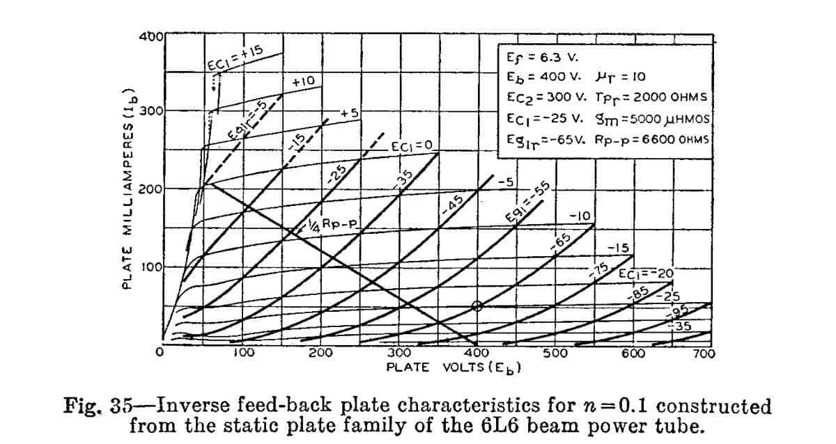
Zen Mod, and in a later post Dr. Mazzola commented on this particular graph [Figure 35] in Schade's paper. It is actually 2 superimposed graphs of the plate characteristics of 6L6; before and after applying his inverse-voltage feedback.
The plate characteristic of 6L6 before feedback [intrinsic] is shown in Figs. 20 and 21. It is graphically similar to the drain characteristics of SJEP120R100 which appears in the Box entitled What goes up must come down of Dr. Mazzola' paper "What's the Buzz?-Part II. I know this graph represents the performance of a voltage-variable current source [per Pass].
The plate characteristic of 6L6 after using inverse-voltage feedback is shown in Fig. 34 of Schade's paper. It is similar to the plate characteristic of a triode, and graphically that of SIT which was liberally described by Pass and Rothacher. I know this graph represents the performance of a voltage-variable resistor [per Pass]
Schade concluded in this powerful and revealing graph of Fig. 35 that "My special style of inverse-voltage feedback [and no other] created the power amp of Fig 33 (c) which performs like that utilizing power triodes instead of tetrodes".
Pass referred in one of his SIT papers that "audiophiles covet the sound of triode tube power amps"; a driver which flared-up the commercial and diy use of SIT. Pass, and DIYer wrenchone have used Schade Feedback in their amps so as to modify the inherent "pentodish" performance of certain semis [MOSFETs, JFETs but not SIT] to that of "triodish". Or a performance conversion a la Schade from a voltage variable current source [plentiful semis] to that of a resitsor [rare SITs].
It follows that Schade style negative feedback may have sonic benefits which audiophiles could covet with a cheap semi, and this special sonic attribute is not endowed or possible otherwise by using overall loop feedback, degeneration etc.
Sorry, I got the F5 and F6 models mixed up.
The F5 does not have any Schade-style fb. It uses standard "series-shunt" (voltage mixing and voltage sampling) feedback.
The F6 may have Schade fb, depending what is going on with all those coupled inductors shown on the simplified diagram. There is also a voltage fb from the output to the input coils which may also constitute Schade fb.
The CSX1 does not have any feedback at all, other than what might be inherently present within the VFETs themselves.
The CSX2 also appears to have no fb at all.
- Status
- This old topic is closed. If you want to reopen this topic, contact a moderator using the "Report Post" button.
- Home
- Amplifiers
- Pass Labs
- SemiSouth boiler room