Schematic (simplified) :
Of course, that type of diff doesn't have stellar high freq. CMRR by design (U2's GBW limiting it), but it works remarkably well in the intended application -- provide a low cost "noise-free" additional high-Z unbalanced input for a grounded (PE==audio GND) device. Gain is always > 1x, 1.33x in this case (a compromise). CMRR is not depending on source output impedance, which was one major design goal.
The main point is the low-side connection of R5 and C2. If it were returned to GND the circuit stops working properly.
Attachments
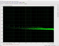
I finally had the chance to do a noise measurement of this fully assembled board that I have a good deal of faith in. Both board and measurement amplifier (within its own enclosure) were connected inside another 3mm aluminium enclosure with power and other cables fed in via small holes.
I shorted the XLR pins 2 and 3.
I got a wideband measurement 22-22kHz of -119.4dBu unweighted, -121.7 dBu A weighted and -122.9 dBu C weighted.
+-15V supplies.
Not bad me thinks...
I shorted the XLR pins 2 and 3.
I got a wideband measurement 22-22kHz of -119.4dBu unweighted, -121.7 dBu A weighted and -122.9 dBu C weighted.
+-15V supplies.
Not bad me thinks...
Attachments
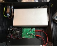
No these measurements were taken in another enclosure - a setup I am using to measure the performance of a voltage regulator I have been working on. I didn't take a pic while measuring the input board but here's a pic of the measurement setup for the voltage regulator which gives you an idea of the setup. I'm simply temporarily repurposing an enclosure I use for my headphone amp. (The measurement amplifier is in the silver box. The voltage regulator is the black pcb. The green pcb is a rail driver used to inject a stimulus frequency into the v-reg. Obviously the latter two were replaced with the input board in this case.)
But this was the crudest part of my measurement setup and the 100Hz pickup was the most volatile component. The supply connector on the board is 4 pole ribbon cable. I needed to connect this to my bench supply and I did so just with cables that had alligator clips at either end. These were exposed / outside the measurement enclosure and so I think were just picking up 100Hz hum from the bench PSU. I should have at least placed the clips at the input board end within the enclosure or used better supply connections.
But this was the crudest part of my measurement setup and the 100Hz pickup was the most volatile component. The supply connector on the board is 4 pole ribbon cable. I needed to connect this to my bench supply and I did so just with cables that had alligator clips at either end. These were exposed / outside the measurement enclosure and so I think were just picking up 100Hz hum from the bench PSU. I should have at least placed the clips at the input board end within the enclosure or used better supply connections.
Attachments
But this was the crudest part of my measurement setup and the 100Hz pickup was the most volatile component. The supply connector on the board is 4 pole ribbon cable. I needed to connect this to my bench supply and I did so just with cables that had alligator clips at either end. These were exposed / outside the measurement enclosure and so I think were just picking up 100Hz hum from the bench PSU. I should have at least placed the clips at the input board end within the enclosure or used better supply connections.
Perhaps I should try to improve this and get an even better performance figure, but my aim was really just to check the implementation. Seems good with better than -119dBu unweighted noise performance (22-22kHz bandwidth).
I finally had the chance to do a noise measurement of this fully assembled board that I have a good deal of faith in. Both board and measurement amplifier (within its own enclosure) were connected inside another 3mm aluminium enclosure with power and other cables fed in via small holes.
I shorted the XLR pins 2 and 3.
I got a wideband measurement 22-22kHz of -119.4dBu unweighted, -121.7 dBu A weighted and -122.9 dBu C weighted.
+-15V supplies.
Not bad me thinks...
unusually it's the even harmonics and fundamental that dominate.What's the cause of the persistent 100 Hz harmonic? I realize it's most likely power-related, but any idea where it's injecting?
One usually sees third and fifth as the dominant interference.
-119dBu is good. That's equivalent to just 0.83uVac over the audio band!
Applying a +60dB Low Noise Amplifier (LNA) to that output increases the noise to 0.83mVac
Try that. amplify and measure.
Last edited:
The output was amplified by Groner's 60dB LNA. I have the nominal gain of 1000 in ARTA. (I need the LNA as my sound card can't measure that low on its own.)
I wonder, could the 100Hz and harmonics be supply ripple? I'm just using my bench supply for this testing rather than the +-15V Aux PSU I built for use in the amplifier itself. I'm open to ideas from you experts...
I wonder, could the 100Hz and harmonics be supply ripple? I'm just using my bench supply for this testing rather than the +-15V Aux PSU I built for use in the amplifier itself. I'm open to ideas from you experts...
what did it measure?The output was amplified by Groner's 60dB LNA. .................
That would be a good check on whether the -119dBu was correct.
I think that's circular...
The screenshot in post 162 is with Groner's LNA in the chain. One enters the gain of the preamp into ARTA. (I can raise or lower the trace by entering a different gain in ARTA.) In testing of the preamp gain/frequency response, I've been wondering if the gain might be a little lower than 1000. If it is, it's not by a lot. Measurement of 1k resistors indicate it's about right. Other tests suggest it might be a fraction low, less than 1dB. (See the Measuring PSRR thread in the Supplies section of the forums.) So far I've decided not to change the gain setting in ARTA from the nominal. +-less than 1dB is fine for me at this stage.
The screenshot in post 162 is with Groner's LNA in the chain. One enters the gain of the preamp into ARTA. (I can raise or lower the trace by entering a different gain in ARTA.) In testing of the preamp gain/frequency response, I've been wondering if the gain might be a little lower than 1000. If it is, it's not by a lot. Measurement of 1k resistors indicate it's about right. Other tests suggest it might be a fraction low, less than 1dB. (See the Measuring PSRR thread in the Supplies section of the forums.) So far I've decided not to change the gain setting in ARTA from the nominal. +-less than 1dB is fine for me at this stage.
Last edited:
You can use a 9k : 10r (or 90k:100r) attenuator to cut the input to the LNA and measure the before and after voltages to see how close the +60dB setting is.
Basic ±1% tolerance of the resistors will give you an accuracy of ±0.74dB
Or use a Harmon divider to calibrate your ratios. A Harmon divider done well can get an amateur into the ±10ppm region at almost no cost.
Basic ±1% tolerance of the resistors will give you an accuracy of ±0.74dB
Or use a Harmon divider to calibrate your ratios. A Harmon divider done well can get an amateur into the ±10ppm region at almost no cost.
See the test in the link in post 171. Unfortunately the resistors were only 2%. Assuming the 11mV from my signal generator was accurate (specs for it here), what's your calculation of gain and accuracy margin? I think my use of the 69.7dB figure is suspect - better to average the individual observations.
(I will have to look up Harmon divider...") Thanks.)
Thanks.)
(I will have to look up Harmon divider...
Thanks.)Sorry mis-spelling
Hamon divider.
C.Hoffman is a Forum Member.
http://conradhoffman.com/HamonResistor.html
using 2% resistors and matched as instructed will give accuracy approaching
BTW,
10k||91k = 9k009901, or ~9k + 0.1% (way better than the tolerance of the resistors).
Don't know why you are using 2% resistors, when 1% metal film 600mW 50 or 100ppm/C are cheaply available.
Hamon divider.
C.Hoffman is a Forum Member.
http://conradhoffman.com/HamonResistor.html
using 2% resistors and matched as instructed will give accuracy approaching
If your resistors have good stability and a low temperature coefficient, 1-2 parts-per-million accuracy is achievable.
BTW,
10k||91k = 9k009901, or ~9k + 0.1% (way better than the tolerance of the resistors).
Don't know why you are using 2% resistors, when 1% metal film 600mW 50 or 100ppm/C are cheaply available.
Last edited:
if you precede your LNA (or any amplifier) with an attenuator and adjust the gain/attenuation to exactly match, then the signal at the input should be exactly the same as the signal at the output. Both frequency and level. Added distortion and added noise may be measurable as a difference.
Now when you measure a signal, you connect a known instrument impedance to two different test points, but each test point has the same frequency and the same level. The instrument should read the same.
Any difference due to the loading effect of the instrument impedance can be calculated.
Now when you measure a signal, you connect a known instrument impedance to two different test points, but each test point has the same frequency and the same level. The instrument should read the same.
Any difference due to the loading effect of the instrument impedance can be calculated.
Last edited:
Yes. As noted above, so far I haven't decided to adjust the gain from nominal as tests thus far indicate it is good enough for my purposes. But indeed it is something on my "to do" list as part of the v-reg testing. Thanks for the heads up regarding Hamon's divider. The test I did to (linked to above) ought to provide some basis for estimation, albeit with greater variance than using 1% (or better) resistors or a Hamon divider. Even accepting the wider inaccuracy introduced by the resistors used (and noting that a more accurate assessment could be done with better resistors), I became very unsure of myself when attempting to use the data produced.
EDIT: by which I mean I ought to be able to calculate from the data I have already produced an estimate of the actual LNA gain and the +- accuracy of that calculation.
EDIT: by which I mean I ought to be able to calculate from the data I have already produced an estimate of the actual LNA gain and the +- accuracy of that calculation.
Last edited:
That's rubbish.You can use a 9k : 10r (or 90k:100r) attenuator to cut the input to the LNA and measure the before and after voltages to see how close the +60dB setting is..................
I should have written 9k99 : 10r for a divide by 1000 attenuation.
I was thinking about a divide by 10 and typed in 9k : 1k for the ratio. Then I retyped it to 9k : 10r, but that is completely wrong !
I decided I didn't need to go to the length of Hamon divider.
I purchased some 0.1% tolerance resistors, 200k Ohms and 20 Ohms, and constructed a simple 80db attenuator. My signal generator has a stated amplitude accuracy of +-2% of set value +- 2mV (1kHz sine wave). I calculated that with an input stimulus from the signal generator of 1dBV (3.174Vpp) this should give me an accuracy of +-2.3% or so. I could lower the accuracy range by increasing the level and thereby reducing the impact of the fixed +-2mV but this is good enough for me. Of course my sound card's frequency response is also a variable.
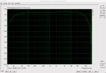
I took 28 measurement readings in ARTA with stimulus frequencies of 50Hz, 100, 200, 300, 400, 500, 600, 700, 800, 900, 1k, 2k, 3k, 4k, 5k, 6k, 7k, 8k, 9k, 10k, 20k, 30k, 40k, 50k, 60k, 70k, 80k, 90kHz. I set ARTA's spectrum analyser to display dBV/SQRT(HZ) with the FFT settings of Fs=192kHz, FFT=131072, Window=uniform (which gave the narrowest peak).
The lowest result was -84.41dBV @ 8kHz while the highest was -80.76 @ 400Hz. The average was -82.00 dBV.
I conclude from this that the gain of my preamp is closer to 58dB and not 60dB, a voltage ratio of 794 rather than 1,000.
I purchased some 0.1% tolerance resistors, 200k Ohms and 20 Ohms, and constructed a simple 80db attenuator. My signal generator has a stated amplitude accuracy of +-2% of set value +- 2mV (1kHz sine wave). I calculated that with an input stimulus from the signal generator of 1dBV (3.174Vpp) this should give me an accuracy of +-2.3% or so. I could lower the accuracy range by increasing the level and thereby reducing the impact of the fixed +-2mV but this is good enough for me. Of course my sound card's frequency response is also a variable.
I took 28 measurement readings in ARTA with stimulus frequencies of 50Hz, 100, 200, 300, 400, 500, 600, 700, 800, 900, 1k, 2k, 3k, 4k, 5k, 6k, 7k, 8k, 9k, 10k, 20k, 30k, 40k, 50k, 60k, 70k, 80k, 90kHz. I set ARTA's spectrum analyser to display dBV/SQRT(HZ) with the FFT settings of Fs=192kHz, FFT=131072, Window=uniform (which gave the narrowest peak).
The lowest result was -84.41dBV @ 8kHz while the highest was -80.76 @ 400Hz. The average was -82.00 dBV.
I conclude from this that the gain of my preamp is closer to 58dB and not 60dB, a voltage ratio of 794 rather than 1,000.
- Status
- This old topic is closed. If you want to reopen this topic, contact a moderator using the "Report Post" button.
- Home
- Amplifiers
- Solid State
- Self's "5532 Low Noise Unity Gain Balanced Input Stage"