Hi Toni
I don't trust my noise test setup enough. I would need to get the DUT into an enclosure etc. Right now both the 27p and 10p versions are reading about -110dBu (20-20kHz) unweighted (-113dBu A weighted). (I wonder if Self had done his noise tests with the DC blocking caps in place and, if so, what value.)
I can look at transients without C7-C10.
ATB
Steve
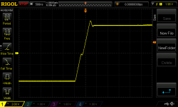
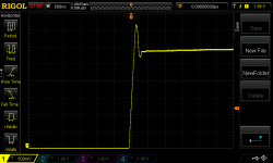
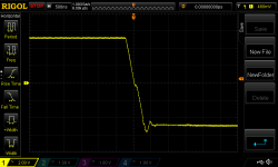
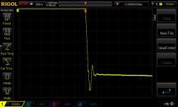
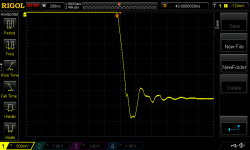
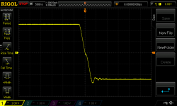
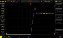
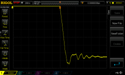
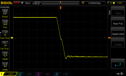
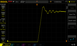
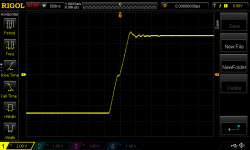
1kHz square 10Vpp, 10p caps, C7-C10 removed
Note, for the zoomed in scope shots I changed the horizontal resolution to 200nS to match post 140.
Removing caps C7 - C10 doesn't look like a good idea to me.
Note, for the zoomed in scope shots I changed the horizontal resolution to 200nS to match post 140.
Removing caps C7 - C10 doesn't look like a good idea to me.
Attachments

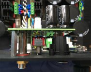
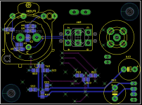
Here's a couple of quick snaps of the board en situe.
If using hex spacers, the required spacer length is 24mm if the XLR and Cardas connector flanges are to meet the PCB. Of course, 25mm spacers are more common and merely require the connectors to be soldered with the board already mounted on the spacers - something I would recommend anyway. (See pic 2 for gap between flange of XLR legs and PCB.)
I had soldered the switch well beforehand as I was using it for testing. Ideally this too would be left until the board is mounted and the switch would be pulled out a little rather than sitting directly with its legs firmly pressed to the pcb. You can see the gap in pic 2 (25mm standoffs). The switch's legs are long enough to close the gap by 2-3mm. (Even without doing so the switch is readily useable from the exterior of the panel. It king of bugs me but given the cost of two new switches I'm not sure it's worth the bother.)
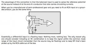
One more thing. Bruno Putzey, in his article dealing with legacy pin 1 problems discusses in section 4.5 how to connect unbalanced consumer sources to balanced inputs.
http://www.hypex.nl/docs/appnotes/pin1_appnote.pdf
He recommends a parallel 100nF/100R RC network from unbalanced cold to chassis. I have not incorporated this directly into the PCB. Each of RCA hot and cold are, by virtue of direct connection to balanced pins 2 and 3, respectively, filtered by 100pF/100R to chassis (via XLR pin 1.) Two questions:
1. I'm puzzled by the configuration recommended - the parallel R and C to chassis - rather than a perhaps more typical one where the signal needs to pass through the resistor. If correct, what are the advantages of such configuration?
2. Are the two RC networks duplicative? That is, given the existence of 100pF/100R is the Bruno RC unnecessary?
If using hex spacers, the required spacer length is 24mm if the XLR and Cardas connector flanges are to meet the PCB. Of course, 25mm spacers are more common and merely require the connectors to be soldered with the board already mounted on the spacers - something I would recommend anyway. (See pic 2 for gap between flange of XLR legs and PCB.)
I had soldered the switch well beforehand as I was using it for testing. Ideally this too would be left until the board is mounted and the switch would be pulled out a little rather than sitting directly with its legs firmly pressed to the pcb. You can see the gap in pic 2 (25mm standoffs). The switch's legs are long enough to close the gap by 2-3mm. (Even without doing so the switch is readily useable from the exterior of the panel. It king of bugs me but given the cost of two new switches I'm not sure it's worth the bother.)
One more thing. Bruno Putzey, in his article dealing with legacy pin 1 problems discusses in section 4.5 how to connect unbalanced consumer sources to balanced inputs.
http://www.hypex.nl/docs/appnotes/pin1_appnote.pdf
He recommends a parallel 100nF/100R RC network from unbalanced cold to chassis. I have not incorporated this directly into the PCB. Each of RCA hot and cold are, by virtue of direct connection to balanced pins 2 and 3, respectively, filtered by 100pF/100R to chassis (via XLR pin 1.) Two questions:
1. I'm puzzled by the configuration recommended - the parallel R and C to chassis - rather than a perhaps more typical one where the signal needs to pass through the resistor. If correct, what are the advantages of such configuration?
2. Are the two RC networks duplicative? That is, given the existence of 100pF/100R is the Bruno RC unnecessary?
Attachments

No takers for the above question?
As an aside and harking back to the size of the DC blocker cap, one of my favourite brands - Theta Digital - has a couple of products deploying Bruno Putzey's N-Core technology: the NC1200-based Prometheus (mono) and Dreadnaught (multichannel) amplifiers. The owner of Theta, ATI Amplifier Technologies, is also soon to release an NC500-based multichannel design. All of these amps are DC coupled as are Hypex's NC400 DIY modules (and presumably Bruno's Mola Mola).
As an aside and harking back to the size of the DC blocker cap, one of my favourite brands - Theta Digital - has a couple of products deploying Bruno Putzey's N-Core technology: the NC1200-based Prometheus (mono) and Dreadnaught (multichannel) amplifiers. The owner of Theta, ATI Amplifier Technologies, is also soon to release an NC500-based multichannel design. All of these amps are DC coupled as are Hypex's NC400 DIY modules (and presumably Bruno's Mola Mola).
The extra cap from unbal cold to Chassis is recommended by many.
I don't know what the extra R does. Interconnected chassis already have, or should have, a link to pass interference current.
eg, two ClassI products have PE to Chassis. There's the link. It is high impedance due to the length of the cables and their inherent inductance.
You can also have another extra cap from unbal hot to unbal cold and/or from unbal hot to Chassis.
Any advantage of the input capacitor for external interference attenuation comes from the location of the cap at the socket entry through the enclosure. Placing the attenuating cap inside the chassis loses some of that advantage. W.Jung discusses this and H.Ott differentiates between external shield connection and internal shield connection. I think it's about what small level of emi can escape from the exposed internal cable.
Your switch is correctly implemented since it does not allow dual operation of bal and unbal. Does it leave minimal capacitance attached to any lead?
Last edited:
It provides a leakage path when connected to "floating" sources which may have high leakage currents, which would overun a diff input with high common-mode impedance (like a THAT120x line receiver).I don't know what the extra R does
would the interconnect cable do that using the source?It provides a leakage path when connected to "floating" sources which may have high leakage currents, which would overun a diff input with high common-mode impedance (like a THAT120x line receiver).
What extra grounding to Chassis benefit does the extra resistor bring?
I have a feeling I am not understanding the problem as you define it.
Last edited:
Could you explain that again?It's also important that one biases (and RF shunts) the hot input with reference to the cold input, not to GND, otherwise CMRR is completely spoiled. Therfore, I tend to use a seperate diff amp for the RCA input and use switch after that.
Any advantage of the input capacitor for external interference attenuation comes from the location of the cap at the socket entry through the enclosure. Placing the attenuating cap inside the chassis loses some of that advantage. W.Jung discusses this and H.Ott differentiates between external shield connection and internal shield connection. I think it's about what small level of emi can escape from the exposed internal cable.
Interesting thought. I suspect aesthetics will drive one towards locating such cap within the enclosure - or better yet follow Bruno's advice in the same document regarding using an adapter cable (whereby cap and resistor are external to the amp).
Your switch is correctly implemented since it does not allow dual operation of bal and unbal. Does it leave minimal capacitance attached to any lead?
The only additional anything resulting from incorporating the unbalanced connection is the switch and traces shown in post 111. I would have thought this would result in minimal if any capacitance attached when balanced operation is selected. It would likely be inadvisable to leave a balanced cable attached when using single-ended input as that would be attached to the circuit.
Here is how I am doing it")
Hi. Why the (extra) caps to chassis on the balanced inputs?
I understand a conventional low pass RC filter (such as the 100R/100p filter in my circuit). I still don't understand how the extra caps to chassis actually filter anything...
PS: Using the switch in your fashion avoids the potential problem I mentioned above of leaving a balanced cable connected when using single-ended sources, but I went for efficiency of PCB trace routing (knowing my bias towards balanced connections).
Balanced input amps (whether fully integrated or made up with op-Amps like Doug Selfs solution) will not handle common mode high frequencies well. They are really designed to deal with frequencies in the audio band, and specifically below a few kHz. The additional caps are the recommended RF filter from THAT corporation. I am getting very good results. The input switching board is located right at the input connectors and the caps connect directly to to the chassis at the connector.
Ok. I think that task is managed in this circuit by the 100R/100pF filter to chassis (via xlr pin 1 to keep the path as short as possible especially given the connectors solder directly to the input board). (BTW I was deterred from using a THAT corporation solution due to a desire to achieve the lowest noise/distortion level possible.)
Regarding gain, I was not interested in trying to balance volume between sources and so left the circuit at unity gain for each of balanced and single-ended sources. I do not envisage a situation whereby inputs are constantly changed.
Regarding gain, I was not interested in trying to balance volume between sources and so left the circuit at unity gain for each of balanced and single-ended sources. I do not envisage a situation whereby inputs are constantly changed.
Attachments
Last edited:
- Status
- This old topic is closed. If you want to reopen this topic, contact a moderator using the "Report Post" button.
- Home
- Amplifiers
- Solid State
- Self's "5532 Low Noise Unity Gain Balanced Input Stage"