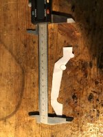
Yust because it is still lying on my desk, here is my gauge for bulding the appropiate carrier, perhaps it helps. Better is to measure by Yourself with an distance of ,6 mil or whatever you propose as X-max or movement of the cone to surface of the driver structure. Don't forget to add some surplus on the right buttom side of the gauge for an install structure with 90 degree bend. I added a 30 degree bend at the structure at frontal view projection to get a nearly horizontal placement in Front of the Driver for optical purposes, some degrees out of horizontal axis are in long terms disturbing ( see
BPTS1590.JPG from last Post).
BPTS1590.JPG from last Post).
Attachments
Last edited:
I would go for this horn, very good bass
https://www.diyaudio.com/community/threads/jericho-cabinet-with-lowther-dx4-help.409569/post-7611812
Big fun horn with pdf
https://www.diyaudio.com/community/threads/jericho-cabinet-with-lowther-dx4-help.409569/post-7611812
Big fun horn with pdf
Hey Freedom, i like Horns too, but did you ever hear the Breezer? I mean with the original obtained 12 mm birchwood? In this Case you have an Sd of nearly 0.7 qm. To get this with a horn affords mutch more efford and Volume. You'll have back reflections into the horn because you will have to shorten the horn beyond ideal what intruduces response inconsistancies as backdraft. Everything is a compromise, Builders have to find the proper compromise for their Needs. Even Jericho is an compromise!