There is a BBC published paper out there somewhere on the thin wall theory. The BBC still buy loudspeakers built to this principle from Harbeth for monitoring use.
This does not mean the theory is correct.
Original BBC research paper is found at the link below. A very large history of highly regarded loudspeakers has resulted from this work... no accident I would suggest.
http://downloads.bbc.co.uk/rd/pubs/reports/1977-03.pdf
http://downloads.bbc.co.uk/rd/pubs/reports/1977-03.pdf
That report makes no claims consistent with what you are saying. I agree with their conclusions completely, but panel thickness is not even mentioned. What is mentioned is damping, which IMO is the most important aspect of the material, but more important is the manner of damping. Damping placed on a panel is no where near as effective as a damped cross brace or CLD. That was not studied - at least not in that paper. Cross bracing was studied in a paper by KEF or someone showing that cross bracing was the key to lower cabinet radiation. Again, I completely concur with THAT result.
And a further paper with plenty of interest contained. (Also mentions constrained layer damping)
http://downloads.bbc.co.uk/rd/pubs/reports/1988-14.pdf
http://downloads.bbc.co.uk/rd/pubs/reports/1988-14.pdf
Last edited:
That report makes no claims consistent with what you are saying.
Low Q thin wall damped panels? I read it as being all about that.
Attachments
Last edited:
Below is Post 239 I made in January, 2015 in the following thread on this forum.
http://www.diyaudio.com/forums/multi-way/235908-how-brace-speaker-cabinet.html
The BBC paper "Factors in the Design of Loudspeaker Cabinet" by H.D. Harwood and R. Mathews is frequently referenced. See the link:
http://www.diy-audio.narod.ru/litr/1977-03.pdf
Harwood and Mathews performed extensive testing and wrote an excellent paper with good insightful analysis. They achieved their goal. They developed a cost effective enclosure, with wall damping, that reduced panel sound emissions to meet their criteria for non-perceptibility. They tested numerous enclosure wall materials and damping configurations. The testing and paper were not intended to develop an enclosure configuration with the lowest possible panel sound emissions.
This paper is frequently referenced by others, sometimes extrapolating its results and crediting it with more extensive implications. I have therefore included some detailed comments, encase one does not desire to spend the time deciphering the paper. Reading this will still take some dedication, sorry. Having a printed copy of the article in hand when reading the comments below would be helpful, almost required. Maybe this material can be condensed again.
Comments:
1) The enclosure panel emission level relative criteria is shown on article page 19, Figure 12, without reference. It is also superimposed on the frequency response plots of the loudspeakers panel sound emission tests.
Relative Level of Enclosure Panels Emission to Loudspeaker Driver Output To Avoid Perceptibility - As given in the Article
100 Hz -13 dB
200 Hz -21 dB
300 Hz - 26 dB
420 Hz -30 Hz
1000 Hz -30 Hz
10,000 Hz -30 Hz
2) Page 7, Table 2 lists the properties of different material for enclosure construction. Harwood & Mathews developed a "figure of merit" (their words) index in the next to last column:
SQRT((modulus of elasticity)(density)/Q x 10EE-5.
Another perspective is: damping x SQRT(Stiffness x Mass)
The greatest values 0.086, 0.085, 0.068, & 0.097 are for lines 15 through 18, and are glass reinforced plastic products. The next highest set of 0.044, 0.43, & 0.042, are for lines 6, 9, & 10 and are for 9mm and 17mm resin bonded birch plywood.
Harwood & Mathews state on page 10:
"...However the figures of merit obtained for the glass reinforced plastic material clearly exceeds that of woodbased types and although the cost is high at present they have the virtue that their cost is not rising as quickly as that of the woodbased products. When therefore an irregular shaped cabinet is being designed the advantages of the type of material should be remembered.
However it should be noted that all of the materials tested are seen to have an excessive Q, the lowest values being about 30. It is therefore evident that additional mechanical damping is required for the panels and under these conditions the natural Q of the material is of much less importance and the values of the characteristic impedance alone are therefore given in the Table (last column)..........it should be noted that the glass reinforced plastic materials retain their first place."
3) Page 12, Table 4, Effects of Damping Treatment on 9mm Birch 7 Ply Along Surface Grain
Q and n damping factor values are listed. n = 1/Q.
Mode Fundamental Q's (second column) of 10 or below represents good damping.
The n fund (thirteenth column), damping factor of the fundamental mode, of 0.100 or greater represents good damping also (remember n = 1/Q).
Only damping treatments for lines 12, 16, and 19 have n fund of 0.100 or greater, denoting good damping.
Line 12 is part of a group, lines 10, 11, & 12 with increasing numbers of layers of Bostik. The damping increases as the damping material thickness increases (1.82 then 3.64 then 5.45 mm), extensional damping principals applied.
Line 16 has me a little puzzled. The 2.9 mm layer of damping material Aquaplas and Thixofix contact cement treatment is well damped with damping factor = 0.100. That's some very effective damping material.
Line 19 is part of a group, lines 17, 18, & 19 of intended constrained layer damping (CLD). Damping material Mutacell is used with Thixofix contact cement and a steel layer. However, Mutacell does not have the desirable shear damping properties for CLD. The damping increases to 0.1428 as the damping layers (4) increases to 7.15 mm. Harwood and Mathews comment on this on page 13.
4) Page 13, Table 6 Effect of Breaks In Damping Layer
Results show the importance of maintaining the integrity of the damping layer for effective damping.
5) Pages 15 & 16, Figures 5, 6, & 7 For Loudspeaker LS 3/6
Figure 5, loudspeaker with erroneously applied one layer of damping material shows slightly increased panel sound output at 200 Hz with "noticeable" & "objectionable" coloration. Figure 6, same loudspeaker with designed two layers of damping, reduced and "permissible" panel sound output at 200 Hz. Figure 7, same loudspeaker with loose stiffening fillets on back panel resulted in broader frequency spectrum with lower output around 200 Hz.
6) Figures 8 & 9 For Loudspeaker LS 3/5
Figures 8 and 9 show the difference in panel sound output when Parana pine fillets were erroneously used instead of the specified beech fillets, with a "audible" and "honky" 9 dB peak at 350 Hz.
7) Figures 10 & 11 Loudspeaker LS 3/4
Figure 10, loudspeaker with inadequate damping resulted in elevated panel sound output at 150 Hz and 490 Hz, with only the smaller 490 Hz peak audible.
Figure 11, loudspeaker with proper damping.
8) Figures 13(a) & 13(b) and 14(a) & 14 (b) Loudspeakers size of LS 3/6, 25" x 12" x 12" (63 x 30 x 30 cm)
Figure 13 (a), loudspeaker 9 mm birch plywood panels, no panel damping, fiberglass fill
Figure 13 (b), loudspeaker 18 mm birch plywood panels, no panel damping, fiberglass fill
Figure 14 (a), loudspeaker 9 mm birch plywood panels, 2 layers Mutcell damping with Aquaseal adhesive, fiberglass fill
Figure 14 (b), loudspeaker 18 mm birch plywood panels, 2 layer Mutcell damping with Aquaseal adhesive, fiberglass fill
Harwood & Mathews comments on page 19:
".....It will be observed that in the case of the thinner wall cabinet, Fig 14(a), the criterion is met whereas it is not met in the case of the thicker walled cabinet, Fig. 14(b). Listening tests confirm these results. Presumably the thicker walled cabinet could be brought within the criterion by the extensive use of much thicker, and therefore more expensive, damping material. Thus, the thicker walled cabinet is more expensive in plywood and in damping material, and is of course unnecessarily heavy, an important point from the outside broadcast aspect. It has no advantages and is clearly an inferior design to that normally used."
I agree with Harwood and Mathews comments, with qualifications concerning the last sentence. If you accept their criteria for panel sound reduction goals, I fully agree.
Looking at Fig. 14(a) and Fig. 14(b), the 160 and 250 Hz peaks of the thinner 9 mm panel have shifted to 230 and 400 Hz for the thicker 18 mm panel, with no change in magnitude. The 18 mm panel has reduced sound emission from 1000 Hz and above. Standard guidelines for application of extensional damping call for a thicker damping layer for a 18 mm panel than for a 9 mm panel.
Comparing Fig. 13(b) to Fig 14(b) reveals the impact of adding the 2 layers of Mutacell damping material (3.85 mm thickness if the same as referenced in Table 4) to the bare panels of the 18 mm speaker. The peaks at 230 and 490 Hz decreased approximately 5 dB, the peak at 900 Hz decreased about 2 dB, the peak at 350 Hz remained unchanged, and the peak at 650 Hz increased 3 dB.
As a general comment, today's high loudspeaker drivers are lowering even order harmonic distortion with improved cones, and lowering odd order harmonic distortion with improve motor designs (shortening rings and contoured pole pieces). Midrange harmonic distortion in the -60 and sometime -70 dB territory has been achieved. Reference SB Acoustics Satori, Scanspeak, Wavecor, Accuton.
--------------------------------------------------------------------------------
Last edited by twinter; 31st January 2015 at 07:21 PM.
Report Post
Last edited:
Box noise
Gedlee good to see you still posting here.
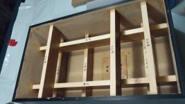
There are a lot of different issues going on here. One key is stiffness of the box which acts as an impediment to absorbing energy. We want the box to be decoupled from the energy of the driver. I get this, see attached image.
But even if this is the case then you still have a lot of energy bouncing around inside. This can form standing waves, which using prime numbers and non parallel sides can somewhat help with (I hear different things from different people).
But then even without standing waves or other additions you still have the energy itself to deal with that if not converted to heat will work its way out in some form.
Thus the energy needs to actually be converted and the usual advice is to use stuffing such as fiberglass and foam etc. I have to say that in all the builds I've done the stuffing aspect was the hardest to get right. The reason is that it always adds a dead muffled sound, I believe because it doesn't equally work on all frequencies. Additionally it can affect the motion of the driver by impeding the flow of energy off of it.
So I'm starting to think that maybe a design like the nautilus which actually draws the backwave out into a cavity so it can't reflect back is the best at least for anything handling higher frequencies.
I don't see why this couldn't be done in a normal square box by just using a brace to bisect and create triangle shape? Or why not just use a big triangle shaped foam wedge pointed at the driver magnet to divided and extinguish the back wave?
Gedlee good to see you still posting here.
There are a lot of different issues going on here. One key is stiffness of the box which acts as an impediment to absorbing energy. We want the box to be decoupled from the energy of the driver. I get this, see attached image.
But even if this is the case then you still have a lot of energy bouncing around inside. This can form standing waves, which using prime numbers and non parallel sides can somewhat help with (I hear different things from different people).
But then even without standing waves or other additions you still have the energy itself to deal with that if not converted to heat will work its way out in some form.
Thus the energy needs to actually be converted and the usual advice is to use stuffing such as fiberglass and foam etc. I have to say that in all the builds I've done the stuffing aspect was the hardest to get right. The reason is that it always adds a dead muffled sound, I believe because it doesn't equally work on all frequencies. Additionally it can affect the motion of the driver by impeding the flow of energy off of it.
So I'm starting to think that maybe a design like the nautilus which actually draws the backwave out into a cavity so it can't reflect back is the best at least for anything handling higher frequencies.
I don't see why this couldn't be done in a normal square box by just using a brace to bisect and create triangle shape? Or why not just use a big triangle shaped foam wedge pointed at the driver magnet to divided and extinguish the back wave?
Attachments
Or why not just use a big triangle shaped foam wedge pointed at the driver magnet to divided and extinguish the back wave?
That's what I've done In my current build, but I used 9mm MDF. Also, the port Is hidden behind It to reduce midrange going through the port.
I don't see why this couldn't be done in a normal square box by just using a brace to bisect and create triangle shape? Or why not just use a big triangle shaped foam wedge pointed at the driver magnet to divided and extinguish the back wave?
That is a common trick to make a highly tapered open or closed midTL. To be effective for bass it would still need to be long.
Foam is not that good an absorber, and certainly not at low frequencies.
dave
Foam is not that good an absorber, and certainly not at low frequencies.
dave
Depends on the foam. Closed cell foam is a terrible absorber and probably the most common. Open cell is much better and with a small PPI, it can be a pretty good absorber. Anechoic chambers use this type of foam.
The idea that non-parallel walls removes the resonances is false. It changes them, but for a given volume there will always be the exact same number of resonances in a given bandwidth.There are a lot of different issues going on here. One key is stiffness of the box which acts as an impediment to absorbing energy. We want the box to be decoupled from the energy of the driver. I get this, see attached image.
But even if this is the case then you still have a lot of energy bouncing around inside. This can form standing waves, which using prime numbers and non parallel sides can somewhat help with (I hear different things from different people).
But then even without standing waves or other additions you still have the energy itself to deal with that if not converted to heat will work its way out in some form.
Thus the energy needs to actually be converted and the usual advice is to use stuffing such as fiberglass and foam etc. I have to say that in all the builds I've done the stuffing aspect was the hardest to get right. The reason is that it always adds a dead muffled sound, I believe because it doesn't equally work on all frequencies. Additionally it can affect the motion of the driver by impeding the flow of energy off of it.
So I'm starting to think that maybe a design like the nautilus which actually draws the backwave out into a cavity so it can't reflect back is the best at least for anything handling higher frequencies.
I don't see why this couldn't be done in a normal square box by just using a brace to bisect and create triangle shape? Or why not just use a big triangle shaped foam wedge pointed at the driver magnet to divided and extinguish the back wave?
The nautilus idea does not cancel or dissipate the back wave, it absorbs it just like any other box stuffing does. The absorption will have almost no effect on the motion of the cone except that it tends to make the box look a little bigger and this has a small effect on the cones motion at resonance. But above resonance the cone motion is going to be relatively unaffected by absorption. And, yes, one does need some absorption inside the box to absorb the internal acoustic reflections, but the enclosures structural resonances are actually the bigger issue if they are not absorbed as well.
That is a common trick to make a highly tapered open or closed midTL. To be effective for bass it would still need to be long.
Foam is not that good an absorber, and certainly not at low frequencies.
dave
Hi Dave, thanks for the reply. So then the question is whether there is any advantage to a triangle or tube shape that terminates as opposed to just a regular speaker box?
IOW lets take two examples. One is just a big box with a a lot of lining and another is a long tube that terminates. Both are lined with the SAME amount and type of lining.
So then will the terminated line more efficiently sponge up (a scientific term) the back energy than a big box? Will the sound in the line still reflect back the way that it does with a typical box speaker? Does anyone have experience with a particular internal shape that is better?
Also something else I was wondering is that if a TL actually converts the back wave to longer wavelengths, then wouldn't this be better at removing the typical box sound since its actually converting the energy. Or is the amount that gets converted inconsequential or creating new problems?
Given the same volume i would guess that a triangle with a terminus out the back would have an edge, fold that with a terminus out the front second, and just a rectangular box last. The waveform need sto pass thru a significant portion of a wavelength of damping to be absorbed. Don’t know for sure where a straight tube out the back would fit, better than a rectangular box i’d think.
We have never done a rectangular box but have used all 3 of the other variants for midTL boxes, all stuffed aperiodically, which one dependent on how it fits with the rest of the box design.
dave
We have never done a rectangular box but have used all 3 of the other variants for midTL boxes, all stuffed aperiodically, which one dependent on how it fits with the rest of the box design.
dave
The idea that non-parallel walls removes the resonances is false. It changes them, but for a given volume there will always be the exact same number of resonances in a given bandwidth.
The nautilus idea does not cancel or dissipate the back wave, it absorbs it just like any other box stuffing does. The absorption will have almost no effect on the motion of the cone except that it tends to make the box look a little bigger and this has a small effect on the cones motion at resonance. But above resonance the cone motion is going to be relatively unaffected by absorption. And, yes, one does need some absorption inside the box to absorb the internal acoustic reflections, but the enclosures structural resonances are actually the bigger issue if they are not absorbed as well.
Hi, thanks for the reply. So let me ask a theoretical question. Let's say you have two bells. And you put one in a large room completely filled with loose stuffing but leave a small gap around the bell. So a stuffed room but the stuffing isn't physically touching the bell.
Then you put the other identical bell in another identical room with no stuffing. I would assume that the room with stuffing would effect the sound of the bell.
IOW the stuffing would allow certain lower frequencies to travel through it well, but certain higher ones would be impeded. This would change the decay times of the higher frequencies and create a muffling effect?
I believe this is what I noticed when I fully stuffed one of my builds. It wasn't crammed in there but certain frequencies sounded "sat on" for lack of a better term.
Maybe the recording studio method of using wedges and non parallel shapes is also applicable to speakers internally.
I read through some of the posts again. It seems that the general consensus is that no "tear drop" or other magic shape will cancel out the backwave. Its just a matter of building solid and having the backwaves bounce around and dissipate with the help of sound absorbers.
I would think that if there was a clearly superior internal shape then all speakers would use it, even if the walls are made out of thin plastic it would still sound better. Dr G. and I think Linkwitz as well said that changing the shape doesn't reduce standing waves (I think this is the resonance being referred to here).
However, something like a t-line has the benefit of drawing some of the energy away from the cone and out as bass energy. How much better this is is debatable.
The physical radiation of the sound would not be affected, but of course since a bell in a room has many refelcetion arriving at the ear the absorption would affect the reflections and change the sound that you heard, but not the direct wave.Hi, thanks for the reply. So let me ask a theoretical question. Let's say you have two bells. And you put one in a large room completely filled with loose stuffing but leave a small gap around the bell. So a stuffed room but the stuffing isn't physically touching the bell.
Then you put the other identical bell in another identical room with no stuffing. I would assume that the room with stuffing would effect the sound of the bell.
IOW the stuffing would allow certain lower frequencies to travel through it well, but certain higher ones would be impeded. This would change the decay times of the higher frequencies and create a muffling effect?
I believe this is what I noticed when I fully stuffed one of my builds. It wasn't crammed in there but certain frequencies sounded "sat on" for lack of a better term.
Maybe the recording studio method of using wedges and non parallel shapes is also applicable to speakers internally.
This is not too scientific of a study so I can't comment on your perceptions.
Shape and placement of the sound absorbing material will have a big effect on its effectiveness. This is because sound is absorbed only when there is particle velocity. At the walls the particle velocity goes to zero so absorption on the walls does little. I always place the absorption in the middle of the box, not on the walls. The box shape will affect the mode shape and move the locations of maximum particle velocity around. A long tube with absorption on the walls won't see so much sound attenuation because the wave motion is normal to the walls. Place it in the middle of the tube and it becomes very effective. So shape is a factor, but any shape can be optimized if you know what you are looking for - hence no shape is any better than any other. Only the implementations vary.
The aim is the same, keep the bass and get rid of the rest. Since it was discovered that an optimal transmission line gives a similar response to a closed box I've stopped building them.However, something like a t-line has the benefit of drawing some of the energy away from the cone and out as bass energy. How much better this is is debatable.
because the wave motion is normal to the walls. Place it in the middle of the tube and it becomes very effective.
That should be "parallel to the walls" - getting too old for this.
The physical radiation of the sound would not be affected, but of course since a bell in a room has many refelcetion arriving at the ear the absorption would affect the reflections and change the sound that you heard, but not the direct wave.
This is not too scientific of a study so I can't comment on your perceptions.
Yeah, not a scientific study. I have to say that there is something less musical about a stuffed speaker. A lot of experienced builders use minimal stuffing. Maybe its just that the stuffing filters out higher frequencies so much better and so has a muffling effect on the sound emanating from the box.
I would assume that sound energy takes a path of least resistance and so something that blocks or slightly impedes the waves can affect the behavior of the source but idk.
This is because sound is absorbed only when there is particle velocity. At the walls the particle velocity goes to zero so absorption on the walls does little. I always place the absorption in the middle of the box, not on the walls. The box shape will affect the mode shape and move the locations of maximum particle velocity around.
This has been my experience. In my first build I tried foam on the walls and fully stuffed and liked neither. No stuffing was okay, but when I tried a flattened pancake of stuffing behind the drivers (horizontally) it was the best sound.
I would think a round beehive of stuffing or f-glass in the middle would break up the axial modes which I assume is a good thing. Then the internal sound would dissipate better with less distortions. Also a ball or slug in the middle would make the internal shape itself less important.
- Status
- This old topic is closed. If you want to reopen this topic, contact a moderator using the "Report Post" button.
- Home
- Loudspeakers
- Multi-Way
- Sealed enclosure -- golden ratio?