Just to avoid any confusion, an ideal PP amp does not remove 2nd. It merely cancels any 2nd generated in the output stage. Distortion from earlier stages is passed on unchanged. Therefore an ideal PP amp will have some 2nd in the output, because ideal amplifiers generate distortion. Only perfect amplifiers (whether SE or PP) generate no distortion.SpreadSpectrum said:Huh? I fail to see where I made any claim that could be challenged. I just claimed I built a p-p amp that has distortion that is 2nd dominated. Obviously I agree that in an ideal p-p amp there would be no 2nd in the output.
For those now confused by the distinction between 'ideal' and 'perfect', by 'ideal' I mean an amp made of components which follow their own ideal model e.g. triodes have constant mu and exact 3/2 law, BJTs are exactly Ebers-Moll exponential (and perhaps with no Early effect?).
Just to avoid any confusion, an ideal PP amp does not remove 2nd. It merely cancels any 2nd generated in the output stage. Distortion from earlier stages is passed on unchanged. Therefore an ideal PP amp will have some 2nd in the output, because ideal amplifiers generate distortion. Only perfect amplifiers (whether SE or PP) generate no distortion.
Absolutely correct. Sorry, I have my head in my own amp design which has a differential input stage and which the remainder is symmetrical. Such an amp will give will give only odd-harmonic distortion in a sim. Thanks for the correction.
If a p-p amp has a single-ended stage at the input, the distortion that stage introduces will of course be faithfully reproduced and added to by the later stages, whether it is even or odd. Also, in real life any imbalance in gain between the two output tubes will generate even harmonics. Only if the two tubes have identical characteristics will even harmonics cancel completely.
But there is more to it than cancellation, right? Let's say that each half of a push-pull pair have non-linearities that
Not sure what happened to the rest of your post - it seems to end in midsentence.SpreadSpectrum said:But there is more to it than cancellation, right? Let's say that each half of a push-pull pair have non-linearities that
PP works by cancellation. The 2nd is still generated in each valve but it cancels in the OPT.
For me all of this discussion is predicated on zero global negative feedback. Cases of transistor amps with ZgNFB, such as the Nelson Pass F5, can indeed match and better what most valve amps have to offer.
Shoog
The F5 does use global feedback.
None of this is undesirable since we want a gentle falling away from second harmonic dominance as displayed in these real world PP amplifiers. If its considered good for SE it would be perverse to consider similar behaviour from PP undesirable and its just another one of those misconceptions laid to rest.
Shoog
Shoog
The F5 does use global feedback.
Its not gNFB, its local feedback.
This is the same kind of feedback we refer to as Schade feedback in valve amps.
Shoog
Last edited:
Its not gNFB, its local feedback.
This is the same kind of feedback we refer to as Schade feedback in valve amps.
Shoog
An externally hosted image should be here but it was not working when we last tested it.
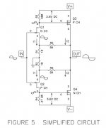
Thanks AJT for posting the schematic. This would be the accompanying text from the manual:
"The feedback mechanism for this amplifier is R3 through R6, a dual pair of low impedance voltage dividers which feed the
output to the Source pins of Q1 and Q2. Low impedance feedback has been (incorrectly) referred to as “current feedback”,
and it is popular in simple high-speed linear circuits. One of the charms of this arrangement is that unlike the classic two
transistor differential pair, the drive current available exceeds the bias of the input stage.
Something different about this example is that each JFET has its own feedback – there are two separate feedback loops to
this amplifier, so that the loop of Q1/Q3 is independent of the loop for Q2/Q4."
The Schade type of feedback (output tube anode to output tube grid feedback) has definitely nothing to do with that topology.
Last edited:
No, read the documentation.
I did after you mentioned it.
Its definitely local rather than global feedback and the text makes that clear.
The concept is what I have used widely in my valve amps. Its the same concept SpreadSpectrum has employed in his example amplifier discussed here.
Shoog
Last edited:
...
Its definitely local rather than global feedback and the text makes that clear.
...
There are two stages in the F5. The feedback goes from the _output_ to the sources of the _input_ transistors. The feedback loop contains both stages, if this is not global what is ?
There are two stages in the F5. The feedback goes from the _output_ to the sources of the _input_ transistors. The feedback loop contains both stages, if this is not global what is ?
Its a subtle difference but the reality is that it goes from the source to the gate of the output stage. Its the same as Schade feedback and that generally understood to be a form of local rather than global feedback.
It is a much more significant issue in valve amps where the OT becomes part of the global feedback loop.
Shoog
Last edited:
Feedback from the output to the source/cathode/emitter of an input transistor looks rather like global feedback to me. Note that there is not a solid dividing line between global and local feedback, although local feedback is often regarded as being around one stage only. Here it is around two stages. It is quite different from so-called Schade feedback, which goes to the output of the preceding stage and so could be regarded as local feedback around the output stage.
So: 'Schade' is local f/b, but this isn't 'Schade'.
So: 'Schade' is local f/b, but this isn't 'Schade'.
There is no "other" version. The schematic AJT posted is the original schematic by Nelson Pass which definitely uses global feedback and bears no relation to Schade feedback.
The simplified schematic by Nelson Pass is no different in this regard BTW.
(It only omits the current limiter and bias regulation.)
The simplified schematic by Nelson Pass is no different in this regard BTW.
(It only omits the current limiter and bias regulation.)
Attachments
Last edited:
There is no "other" version. The schematic AJT posted is the original schematic by Nelson Pass which definitely uses global feedback and bears no relation to Schade feedback.
If you read the article there is a schematic just above the text which AJT posted. Go check it.
He included it so that he could describe the concepts more clearly without all the added complexity of the helper components.
Shoog
If you read the article there is a schematic just above the text which AJT posted. Go check it.
He included it so that he could describe the concepts more clearly without all the added complexity of the helper components.
Shoog
See above.
There is no direct feedback from the drains to the gates of Q3 or Q4.
Last edited:
- Status
- This old topic is closed. If you want to reopen this topic, contact a moderator using the "Report Post" button.
- Home
- Member Areas
- The Lounge
- SE distortion