Never had this issue as I design with a load resistor to prevent it, and if you use the proper dropping resistor you get a window of about 40ma to work with. I use one 0A3 for 4 6P3S tubes without any issue.If you used a gas tube as a series voltage dropper, wouldn't you have issues when tubes went into cutoff and then started to conduct again? The voltage across the gas tube would vary as it would have to strike again.
I mean, variations of B+ voltage cause wider variations of G2 voltage as the result.
Variations of B+ are caused both by variations of voltages in power outlets, and by variations of current consumed by tubes in amps working in class AB.
I understand what you mean although it would move around even more using a simple dropping resistor and a cap, no?
Here's an idea. Tie the 0A3 to plate instead of B+ and see if you can make a "super triode".
I understand what you mean although it would move around even more using a simple dropping resistor and a cap, no?
Differently. With dropping resistor when the amp is PP it would depend on sum of currents.
Here's an idea. Tie the 0A3 to plate instead of B+ and see if you can make a "super triode".
I prefer pentodes with feedback to G1.
One: yes it is. As said it's class A, average == peak.
Two: A voltage divider would work if all the resistors were the same value and the current draw was constant.
#1) What happens when you clip? Ever put a meter on your house's AC?
#2) Please, please indulge me with an example. Kirchoff is ready to roll.
If it has to be octal, I'd recommend plugging a mosfet into an octal socket. Then you can reference the heater to whatever you want since you won't use it anyway.
But seriously, I do use simple mosfet followers as screen regulators all the time. It is very similar to what is being done in this schematic. If I were to do it with a tube I would probably use an EL34 since it is in production, inexpensive, and has high transconductance.
I have one running that is just a MOSFET hung off a voltage divider. The gm of the MOSFET is apparently adequate, but an improvement is in order. Tie a CCS between the regulator 'FET and ground. Bump the idle current through the 'FET, and therefore its gm a bit( enough to be worthwhile IMO ). Heatsink adequately of course. The CCS will be dissipating across g2 voltage, and the 'FET will have B+ minus g2 voltage across it...
")
Or put a resistor there...it is *SOMETHING* to pass a bit more current, and bump the gm of the pass device. Getting the 'FET delivered gm above a high-gm pentode or triode should be about as easy as fishing in a seafood market...
I don't like the idea of what is effectively *ANOTHER* amplifier( the error amp and active voltage ref ) in series with the main circuit. Simple seems to be working quite well.
cheers,
Douglas
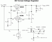
OK, having managed to receive a 6AV5GT tube as screen regulator. In the Leak schematic the heater is connected to B+ anode voltage so I wonder if that could give AC heater hum on the anode voltage?
This tube has only 4.3 triode amplification factor so is this acceptable for good regulation (the LEAK circuit doesnt have an error amp anyway). Maybe LEAK would have aimed for a small regulation factor but mainly for screen noise reduction with the KT61 regulator tube?) Im not sure exactly what benefits the circuit becomes when using this regulator tube instead of a simple voltage drop resistor? Have never seen this screen regulation on famous Klangfilm amps
This tube has only 4.3 triode amplification factor so is this acceptable for good regulation (the LEAK circuit doesnt have an error amp anyway). Maybe LEAK would have aimed for a small regulation factor but mainly for screen noise reduction with the KT61 regulator tube?) Im not sure exactly what benefits the circuit becomes when using this regulator tube instead of a simple voltage drop resistor? Have never seen this screen regulation on famous Klangfilm amps
> this regulator tube instead of a simple voltage drop resistor?
It is not a regulator. The plate supply is higher than the Screen wants/needs/stands, so they used a simple 2/3 divider, buffered for less sag.
The few-hundred Ohm impedance of a fat bottle's cathode is unimportant here.
Simple resistor is no-good because Screen current changes a lot from idle to full blast. Apparently 12mA to 24mA for some suggested condition. The 12mA change, times <500r cathode impedance, is 6V shift; negligible on a 300V screen. OTOH, for a 445V-300V drop with simple resistor we need 12K at idle and 6K at full roar. If we just used 12K, then the drop wants to double at full roar, 155V on Screens, which would suck.
> heater is connected to B+ anode voltage
No- it is connected to screen supply which IS cathode voltage, enforcing ZERO heater cathode voltage, no heater leakage and hardly any AC hum on Vg2. Which isn't too important anyway since push-pull tends to cancel hum on Vg2 supply.
Many thanks for your explanation. I always thought that screen voltage and therefore screen current should be stable and does not swing like anode current?
If this KT61 screen tube is no regulator, how could it make screen voltage more stable as a simple resistor?
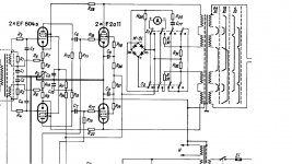
Is the big Klangfilm V69 amp (push pull F2A with voltage dropping screen resistor) therefore an example for a worse technical solution and the LEAK TL25 with tube in screen supply the preferred solution?
At last, my design is not PP but a SET power amp. So I think the screen voltage varies the same in class A as the PP design in class AB?
If this KT61 screen tube is no regulator, how could it make screen voltage more stable as a simple resistor?
Is the big Klangfilm V69 amp (push pull F2A with voltage dropping screen resistor) therefore an example for a worse technical solution and the LEAK TL25 with tube in screen supply the preferred solution?
At last, my design is not PP but a SET power amp. So I think the screen voltage varies the same in class A as the PP design in class AB?
Attachments
Last edited:
If this KT61 screen tube is no regulator, how could it make screen voltage more stable as a simple resistor?
He already explained. Output dynamic resistance of a cathode follower is lower than of the voltage dropping resistor that would be needed, so current variations of screen grid current causes lower variations of screen grid voltage.
Hello,
I want to use screen grid regulation with an octal tube on my SET F2A project.
Leak did this on the TL/25A. I rarely seen this method.
Could someone please recommend a usable tube (not KT61 please, too rare and expensive) and a circuit mod for 15mA screen grid regulation? Will it be worth the effort? Many thanks in advance.
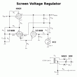
Screen regulation for pentode finals is definitely worth it, though seldom seen except in professional equipment. even the active decoupler shown in the schemo is a rare bird.
I prefer active regulation, either hollow state of solid state. I have a couple of "go to" designs for this. If you want an Octal type, then the 6V6 is electronically identical to the 6AQ5 used here as the series pass device. You do have to watch that VHK on the series pass tube: it isn't all that high, and it's best to power the regulator heaters from a dedicated heater xfmr.
Attachments
- Status
- This old topic is closed. If you want to reopen this topic, contact a moderator using the "Report Post" button.
- Home
- Amplifiers
- Tubes / Valves
- Screen regulation with tubes