Hello,
I want to use screen grid regulation with an octal tube on my SET F2A project.
Leak did this on the TL/25A. I rarely seen this method.
Could someone please recommend a usable tube (not KT61 please, too rare and expensive) and a circuit mod for 15mA screen grid regulation? Will it be worth the effort? Many thanks in advance.
Attachments
Last edited:
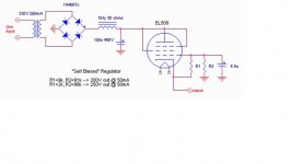
Thank you. How has the biasing of this regulator tube been done? The grid has 296VDC above ground so I assume the cathode potential has to be approx. 300VDC as output voltage for push-pull tubes but the heater is 6.3VAC without connection to ground. Is this correct to have a free flown 6.3V AC heater connected with a cathode 300V DC above ground?
I got flamed a few years back for calling such a scheme a regulator because it does not have an active voltage reference; I guess you are more popular than I am ")
Consider adding an active voltage reference, or adopting a more sophisticated regulator with an active voltage reference.
Consider adding an active voltage reference, or adopting a more sophisticated regulator with an active voltage reference.
Sounds like a good place to use a sweep tube. Get an active screen reference going for the pass tube, and you will get a nice low impedance regulator with reasonably better regulation due to the lower impedance. something like a 6AV5GA or 6BQ6, or even better, a 6DQ6 or similar would be a nice start. I would have a perverse desire to use a CCS loaded VR tube as the voltage reference, but that's just me
Even a 6V6 or similar would work well, but I would want lower plate impedance for better regulation, so would probably step up to at least a 6L6 or something.
Even a 6V6 or similar would work well, but I would want lower plate impedance for better regulation, so would probably step up to at least a 6L6 or something.
300VDC as output voltage for push-pull tubes but the heater is 6.3VAC without connection to ground. Is this correct to have a free flown 6.3V AC heater connected with a cathode 300V DC above ground?
In the Leak schematic the heater appears directly connected to the cathode (pin 7 adn 8 are connected) so it is at 300V which is fine.
If it has to be octal, I'd recommend plugging a mosfet into an octal socket. Then you can reference the heater to whatever you want since you won't use it anyway.
But seriously, I do use simple mosfet followers as screen regulators all the time. It is very similar to what is being done in this schematic. If I were to do it with a tube I would probably use an EL34 since it is in production, inexpensive, and has high transconductance.
But seriously, I do use simple mosfet followers as screen regulators all the time. It is very similar to what is being done in this schematic. If I were to do it with a tube I would probably use an EL34 since it is in production, inexpensive, and has high transconductance.
How does it lead to instability of B+? It's still 75V lower than B+ which for a 6L6 for example means 400V plate, 325V screen. Works perfectly fine IMHO. Not to mention B+ isn't supposed move around much. This is why people like me use a large choke, and large caps, and design primarily in class A. Easy to design a supply this way, and it virtually eliminates the tetrode kink.
Last edited:
Not to mention B+ isn't supposed move around much.
#1, this isn't true
#2, if it it was true, then an active voltage device is pointless, as a resistor divider would also drop a constant 75V
If you used a gas tube as a series voltage dropper, wouldn't you have issues when tubes went into cutoff and then started to conduct again? The voltage across the gas tube would vary as it would have to strike again.
But really, I have done the mosfet thing over and over and it works just fine for screen regulation. There is no reason a tube wouldn't work pretty well in that scheme too if you really wanted to do it that way.
But really, I have done the mosfet thing over and over and it works just fine for screen regulation. There is no reason a tube wouldn't work pretty well in that scheme too if you really wanted to do it that way.
SpreadSpectrum,
Are you using an enhancement or depletion mode FET? In the latter case the equivalent of the tube 'regulator' may be used, but is not really a regulator as Wavebourn has pointed out, but only a low impedance screen voltage supply. (This will cause improved regulation from screen current variations, but will still be at the mercy of h.t. variations.)
In using a zener string to stabilise the gate one needs to be aware of the temperature dependance/factor of high voltage zener diodes.
Johan,
I use enhancement mode devices as they are cheaper. It just changes the voltage at the source by a little bit and can be easily accounted for. Of course, I am using the term "regulator" loosely here. It is of course just a voltage follower. I'd take the additional step of bypassing the lower resistor in the divider string with a cap to reduce ripple at the gate/grid of the "regulator".
I would use zeners in the reference string only if the bias supply were stabilized and I would never use zeners/gas tubes in the top of the string as that would make voltage fluctuations as a percentage of output voltage go up as Wavebourn pointed out.
Oh and my comment above was me responding to kodabmx's comment which I obviously misread. I thought they were suggesting dropping only through the gas tube without any path for current to flow when tubes were in cutoff. Obviously, this is not the case. I must have been in a hurry when I read that initially.
-Heath
#1, this isn't true
#2, if it it was true, then an active voltage device is pointless, as a resistor divider would also drop a constant 75V
One: yes it is. As said it's class A, average == peak.
Two: A voltage divider would work if all the resistors were the same value and the current draw was constant.
And especially a since IMHO a well designed power supply will deliver at least twice the current required, and the fact that my amps feature about 3500uf of capacitance through a choke input, no this isn't an issue. Maybe for a cheap kit amp from China though, but not from me.
When an amp requires about 200W of power, and the supply is good for 400W a 10W load doesn't effect it.
- Status
- This old topic is closed. If you want to reopen this topic, contact a moderator using the "Report Post" button.
- Home
- Amplifiers
- Tubes / Valves
- Screen regulation with tubes