That is the Western Electric 'Harmonic Equalizer' I mentioned on post #15, original WE 300A PP type WE86 amp use 60R and WE92A amp use 85R in your R30 position. You may want to simulate higher values like 30-120R. Lynn Olson suggested adjustment by distortion measurement and listening.... I also added this 10R resistor highlighted on red square. I don't know what it's called but it helps to reduce THD considerably.
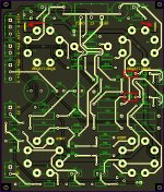
Peter Millett use ground planes, but done incorrectly will introduce high stray capacitances and signal loops that could cause unwanted noise, ringing, oscillations, phase shifts or distortion. There is a reason that many still use P2P. Better take your time and reevaluate where 0.5mm clearance is good enough and where to add a good deal more, especially around grids and traces with high current/voltage. I have seen PCB design with ventilation holes drilled around output tube sockets but I prefer to separate output tubes to chassis mounting to minimize thermal issues that may also affect other components such as electrolytic capacitors and SS.As can be seen, i'm using ground plane and route all the power-related traces on the same side while signal traces on the other. I set 0.5mm clearance from the ground plane to other traces. I seem to recall that ground plane is not advisable in tube project PCBs? Is this correct?
I think it is advisable to breadboard and debug problems before committing to a PCB. A double sided through hole plated FR4 PCB is no peanut money. Just my 2c.Next target will be to getting all the parts, measure their physical dimensions and adjust the PCB as necessary.
+1, until it is fully debugged, there is no point rushing the PCB design - I am not even sure why you would need it for an one-off build, or perhaps you got bigger plans...I think it is advisable to breadboard and debug problems before committing to a PCB.

How do you determine the sweet spot George? By ears or measurement
Both. I will usually set the bias and offset while measuring distortion at a low frequency (20 to 50 Hz depending on what the OPT can take) and a power level where I intend to operate the amp. Then retest at 1 KHz and 10 KHz. Often the final adjustment is a compromise and can be affected by the output tubes. Crummy OPT's that are off balance at high frequencies can sometimes be helped with a small silver mica cap, or cap and resistor in series, across the primary on one side. These components will see at least TWICE the B+ voltage (4 X in a guitar amp) and must be rated as such.
If the amp is a prototype and I'm likely to keep messing with it, I'm not picky. I set it close enough, and move on.
If the amp is a finished piece, and it's going into my system, I have been known to spend a day or two tweaking. I will optimize the driver up to the grids of the output tubes with an FFT analyzer, a HP8903A audio analyzer, and a scope, for the lowest distortion at my intended power level across the audio band, then forget it.
If I have built an amp for myself, chances are I have a box full of output tubes that will fit it. I will then select a batch based on this method.
Sometimes the tubes are all similar, but most of the time they aren't. Tubes that have been sleeping for years need to be run for several hours before using. I just hook them up to a power supply at the intended operating voltage, set the bias current and leave them to cook. If the bias drifts around, vote them off the island......find a batch of stable tubes that take about the same grid voltage to get the current that you intend to operate them at.....that's better "matching" then you get from most vendors that "match" tubes in a tube tester.
Then I will start rolling through that batch of output tubes in the amp to find a set with the lowest distortion and best sound ( HiFi amp), or most power and best sound (guitar amp). I will set the bias, offset, and any other adjustments available using the test procedure outlined above.
Then it's hook up the speakers and listen time. There WILL be a digital storage scope across the speakers to confirm things I hear. Sometimes I like what I hear, sometimes I mark all the adjustments so I can come back to those settings, and turn knobs to see how the sound is affected. Listen to big bass sounds for signs of OPT saturation. Use music with sustained sinusoidal sounds so you can watch the scope. Tweak the offset if saturation is seen / heard. Listen to transients like the sound of a drum stick whacking the rim of a snare drum. Do they sound realistic.....drum transients are hard to get right. My daughter played the drums in high school, and I still have her drum set. Listen to high frequencies, like cymbals played with a brush. To they sound real? Tweak the high frequency offset if available, and the compensation cap if GNFB is used.
You made all the adjustments with a resistive load on the amp. You speakers are NOT a resistive load and will not be at their rated impedance with real music applied to them. It is normal to see unclipped peaks way above the amps normal output power rating in the bass region. This may invoke OPT saturation at power levels below the amps rating, or it may allow VOLTAGE output well above the amps expected output without clipping, especially on an SE amp. This is because the speaker might be 15 to 30 ohms in the bass region.
I have discovered a simple hack to get the offset close especially in a fairly high powered amp. Ever notice sound coming from the OPT while testing into a dummy load? Crank the amp into a dummy load at 1 KHz, or a lower frequency if the OPT is loud enough, and adjust the balance for minimum sound. I have found this to be relatively close to the ideal setting on many amps.
The decision for direct-to-PCB is from me adapting to my situation. I work away from my hometown and can only do this hobby within a narrow time window on weekends when i am back so i try to do as much as i can when i am away. For me this translates to PCB. Much shorter time assembling on PCB than breadboarding. So far it works for me. If it does fail, that's 10 USD i am willing to pay for the potential time saved. I saved a lot by importing parts myself and avoiding boutique ones so i guess i can afford to lose a bit here.
The decision for direct-to-PCB is from me adapting to my situation.
That was my situation for a few years a while back. I spent a lot of time travelling, and sitting around in places like cars, airplanes, doctors offices, and hospitals while my mother in law was terminally ill. My laptop went with me, and I committed a bunch of my ideas to LT Spice simulations, and made PCB's for the ones that looked feasible. I still have a bunch of PCB's to make and test.
I seem to recall that ground plane is not advisable in tube project PCBs? Is this correct?
As with PTP wiring, ground is usually your friend. I usually set the defaults on vacuum tube PCB's to 50 mil (1.2mm) traces with 50 mil minimum spacing. Fatter traces for heater wiring on output tubes. Minimum pad size is 100 mils (2.5mm), larger where possible. Some of my PCB's may become Tubelab products, and those are good for inexperienced builders. I put ground plane wherever I can, but avoid it directly opposite a high impedance trace where a few extra pF can create a high frequency roll off.
I recently retired from a 41 year engineering career at Motorola where one of my functions was to design and layout PCB's for prototypes. Often things like cell phones and two way radios using tiny SMD parts at frequencies up to 2.5 GHz. Tube amps are polar opposites of these things, but by no means simple. The same things that work in PTP design are needed in a PCB, but the voltage levels and impedances are much higher than a cell phone, so the constraints are quite different.
I have discovered a simple hack to get the offset close especially in a fairly high powered amp. Ever notice sound coming from the OPT while testing into a dummy load? Crank the amp into a dummy load at 1 KHz, or a lower frequency if the OPT is loud enough, and adjust the balance for minimum sound. I have found this to be relatively close to the ideal setting on many amps.
another trick added to my bag of tricks, thanks tubelab.....

In that case, I suggest a little more simulations to consider other schemes. I noted other effective feedback scheme as expressed by kenpeter here and shown by revintage as example here relevant to your case.... I work away from my hometown and can only do this hobby within a narrow time window on weekends when i am back so i try to do as much as i can when i am away. ...
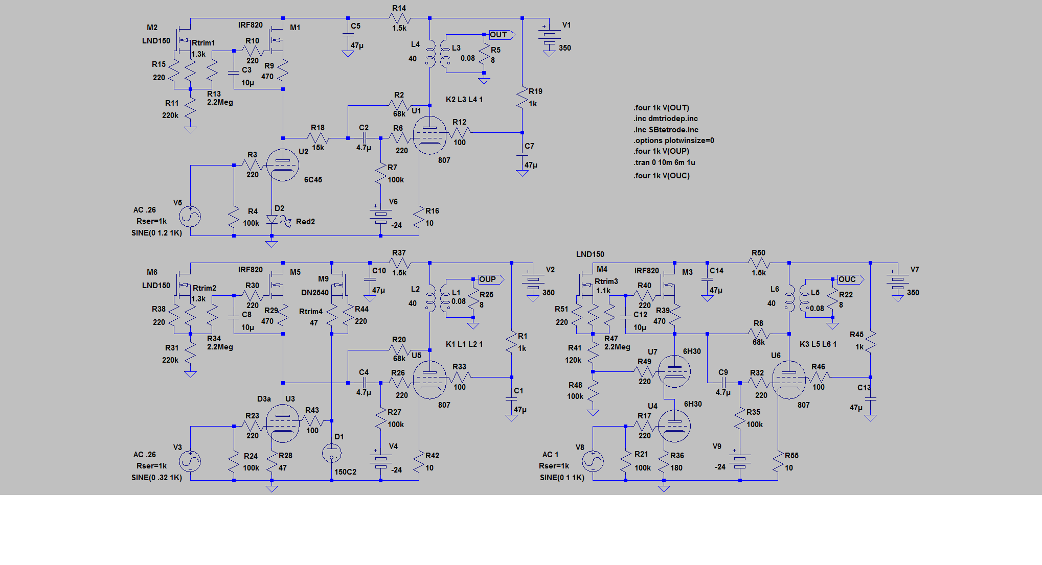
Please note the use of R18 in relation to R2 feedback on top left scheme theoretically exhibit better distortion behavior.
You may also find that for your scheme on post #36, a 220-1000uf capacitor in series with a 60-200R connected from cathodes of V2 to ground will reduce distortion.
V-I converter (R18) before going to I-V converter (R2). Interesting. Yes it would be a better scheme.. I'll give it a thought. I haven't simulated it yet but i imagine it will need more swing compared to the usual plate to plate resistor. What i really need is twin EF86 pentodes in a single envelope octal base.. lol. That way i can keep the octal spirit and provide better Schade scheme.
John Broskie writes a whole article about this schade feedback. If I understand it correctly, then R2 is the I-V converter. Just like IV converting op-amp we usually found on current output DAC like TDA1541, only with weak open loop gain.
Found it:Tube CAD Journal March 2001 Page 4
Found it:Tube CAD Journal March 2001 Page 4
John Brosky writes a lot. He likes to write.
This feedback is not "schade", Otto Schade in his famous article back in 1938 proposed to add feedback to 6L6 tube to make it usable for audio. He used series feedback by voltage through an input transformer. Here is parallel feedback by voltage. Feedback makes an amp more linear when it's divider is linear. It is the basic. It is plain dump physics, it can't be replaced by even most colourful belletristic.
This feedback is not "schade", Otto Schade in his famous article back in 1938 proposed to add feedback to 6L6 tube to make it usable for audio. He used series feedback by voltage through an input transformer. Here is parallel feedback by voltage. Feedback makes an amp more linear when it's divider is linear. It is the basic. It is plain dump physics, it can't be replaced by even most colourful belletristic.
Hi Anatoliy,
Some points are still unclear to me. If we replace the gyrator on the 2 pictures on the bottom on post #47 with a high value resistor (or remove it altogether), we also get the plate impedance back into the equation. I've seen quoted nice results from these like Gary Pimm's 47 PP with driver biased with current from the feedback resistor and Michael J Koster drive the grid of the output tube from gyrator mu output while feedback resistor was connected to plate of the driver, while theoretically a linear resistor divider is preferred. Could you share your findings and opinion a bit more on this plate to grid feedback scheme?
Some points are still unclear to me. If we replace the gyrator on the 2 pictures on the bottom on post #47 with a high value resistor (or remove it altogether), we also get the plate impedance back into the equation. I've seen quoted nice results from these like Gary Pimm's 47 PP with driver biased with current from the feedback resistor and Michael J Koster drive the grid of the output tube from gyrator mu output while feedback resistor was connected to plate of the driver, while theoretically a linear resistor divider is preferred. Could you share your findings and opinion a bit more on this plate to grid feedback scheme?
Pentode or cascode with high plate impedance have to be loaded on a resistor of relatively small value. It's value with "feedback" resistor forms a voltage divider that sets the feedback ratio. But actually the pentode is loaded on even lower resistance, since it sees a dynamic resistance of the feedback resistor divided by an amplification factor of the output tube. If say amplification factor of the output stage is 10, the pentode is loaded already on 68k/10 = 6.8k resistance. What's the point of the gyrator?
Thanks Anatoliy.
I think of the use of a gyrator as a way to fix bias voltage allowing use of driver at higher current and/or as a modified source folower for A2 or screen drive. I just realized that implementation needs very careful consideratons since introduced nonlinearities could easily outweigh the advantages.
I think of the use of a gyrator as a way to fix bias voltage allowing use of driver at higher current and/or as a modified source folower for A2 or screen drive. I just realized that implementation needs very careful consideratons since introduced nonlinearities could easily outweigh the advantages.
John Broskie writes a whole article about this schade feedback. If I understand it correctly, then R2 is the I-V converter. Just like IV converting op-amp we usually found on current output DAC like TDA1541, only with weak open loop gain.
Found it:Tube CAD Journal March 2001 Page 4
What Broskie is describing here is more like E-Linear, not parallel (aka "Schade") feedback. Parallel lNFB is implemented like this: (attached). Rf isn't doing double duty as a plate load. It does, however, accomplish the same end: linearizing a less than linear type so's you can take some of the pressure towards instability off the main gNFB loop by substituting a much shorter feedback path that contains less phase shifting reactances.
I did it this way as opposed to the E-Linear method since 5SL7s aren't real good when it comes to current sourcing, especially when the grids of the finals want to slip into Class AB2 on peaks that overdrive the grids. As a side benefit, I was able to get a few more watts of output as well. (32W as opposed to the specced 26.5W. @ 1.0KHz)
Attachments
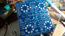
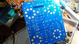
I have decided that i will keep the feedback network for now. I made some minor changes to the PCB:
1. Added some jumpers to the heater trace to allow swapping between 6V and 12V heater for the output tube. It allows me to switch between 6BQ6 and 12BQ6 and, should they become too expensive, 6P31S.
2. Added zener diode under the G2 drive source follower to allow some voltage shift and make the PCB a bit more universal. This will be a jumper as i am using the same B+ for driver and output stage.
3. Adjusted electrolytic cap dimension to the actual ones i'm using.
If there is no major mistake, i will send this design to the PCB fabricator.
Attachments
I want to decide on the rating for the 220V isolation transformer. Can someone confirm if my calculation is correct?
Based on LTSpice simulation, peak current consumption per channel when pulling 40W is 500mA. So that's 1000mA for both channel. This means the average current consumption is 1000/1.414 = 707mA.
Power consumed is then 300VDC x 707mA = 212W for both channel. Since i won't be pulling 40W all the time, i assume i can reduce this a bit. So will a 150VA isolation transformer suffice?
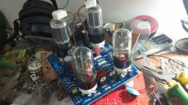
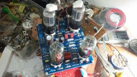
Just want to give a small update to this project. PCB's finally done (after the fabricator had to remake it as there was drill diameter mistake).. Two hours later, finished one channel for trial. Power supply is coming up next.. I have the 150VA 220V isolation transformer.. some SS diodes with several 400V caps is on the shopping list.
Attachments
- Status
- This old topic is closed. If you want to reopen this topic, contact a moderator using the "Report Post" button.
- Home
- Amplifiers
- Tubes / Valves
- Screen Drive 6BQ6GT Amp - Feasibility Study