Re: Re: I would wish view your pcb for BPA200
Zang you know I love your work, but I have to pick on you..
So what's the difference between a Chinese pencil and a "regular" pencil? I would assume just the decorations on the out side?
I'm glad to see you active on the forum again.")
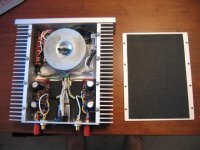
digi01 said:the upper thing of the photo is a chinese pencil
Zang you know I love your work, but I have to pick on you..
So what's the difference between a Chinese pencil and a "regular" pencil? I would assume just the decorations on the out side?
I'm glad to see you active on the forum again.
thanks all I am happy!
and sorry for slow response,I am very busy for spring exam.hopefully it could be passed smoothly
P.S.
here is PDF version,including some others project.
http://digi01.hk.st
Z
I am happy!and sorry for slow response,I am very busy for spring exam.hopefully it could be passed smoothly
P.S.
here is PDF version,including some others project.
http://digi01.hk.st
Z
Maybe half the chips but the thermal power for one lm4780 can reach values so that your'e in need of a cooling fan. It's much better to spread the power discipation to more chips!
(For ex. you can't use the LM4780 in bridged configuration without a fan . Even a giant heatsink couldn't take all the heat the LM4780 produces in bridged mode; the contact area of the chip is too small. For me only PA-equipment should be cooled with a fan.)
(For ex. you can't use the LM4780 in bridged configuration without a fan
. Even a giant heatsink couldn't take all the heat the LM4780 produces in bridged mode; the contact area of the chip is too small. For me only PA-equipment should be cooled with a fan.)slackman said:Maybe half the chips but the thermal power for one lm4780 can reach values so that your'e in need of a cooling fan. It's much better to spread the power discipation to more chips!
(For ex. you can't use the LM4780 in bridged configuration without a fan
Making two boards, each paralleling three chips ("6" total), then bridging the two boards, should be able to handle it. Or if you don't feel like getting that fancy, parallel 2 chips ("4" amps total), then bridge those.
I know there are some folks using BrianGT's LM4780 kit in BPA without fans.
motherone said:Digi,
Have you considered doing a BPA layout using the 4780? Half the chips would be needed!
Mike
thank you,I would not take more time on chip amp.I am going to digital & solid
P.S.
All per order has send out,feel happy to test it and post your review and comment. THANKS
Zang
Hi Zang,
I'm still waiting for arrival of my boards, however
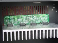
when I trace the copper track on the PCB in the photos
attached in Post 18, it indicates that the U7 output is
connected to the NI input (pin 10 via pin 11) of all 4
power chips (U1 - U4).
Please clarify
Thanks
TS
I'm still waiting for arrival of my boards, however
when I trace the copper track on the PCB in the photos
attached in Post 18, it indicates that the U7 output is
connected to the NI input (pin 10 via pin 11) of all 4
power chips (U1 - U4).
Please clarify
Thanks
TS
TS Lo said:when I trace the copper track on the PCB in the photos
attached in Post 18,...
thank you mention it
I have got a big prize the eval board has a bug.I have check out it.
rgds
Zang
- Status
- This old topic is closed. If you want to reopen this topic, contact a moderator using the "Report Post" button.
- Home
- Amplifiers
- Chip Amps
- scratch BPA200 pcb lay out