For the CFB case, starting with the conventional configuration with an RL (90% in the plate, and 10% in the cathode, 250 V B+):
Vp = 250 - (0.9 * RL * Ip)
and Vk = 0.1 * RL * Ip
solving for RL = 10 Vk / Ip
and then eliminating RL from the equations:
Vp = 250 - 9* Vk
so then Vk = (250 - Vp)/9
So that eliminates the RL problem.
Just sweep Vp as before (but just 25 to 250 V, since Vk gets added to make the 250V max),
and so Vk = ARB1 = (250 - Vp)/9
Unless I goofed somewhere.
Last edited:
I change Vk = ARB1 = (250 - Vp)/9, the result is still about the same. I also removed the bias, and just sweep the grid like the Schade case from 0V to -100V:
An externally hosted image should be here but it was not working when we last tested it.
One thing I see is that we need to have a floating screen supply referenced to the cathode on the cathode feedback case for these to be equivalent.
In other words, the cathode feedback case is not acting strictly as a pentode like the Schade case since the screen supply is not referenced to the cathode. Screen voltage is varying with signal.
In other words, the cathode feedback case is not acting strictly as a pentode like the Schade case since the screen supply is not referenced to the cathode. Screen voltage is varying with signal.
Last edited:
Also, we see the same upward slope in the bottom of the characteristics in the Schade characteristics that we see from the curve tracer plots due to the load and alternative current path that the feedback network presents.
You could buffer that for the purposes of this simulation and that should make it so that they should line up better in that respect.
You could buffer that for the purposes of this simulation and that should make it so that they should line up better in that respect.
Sure, I did try that, but it made very little difference... also as far as I can tell, CFB in actual amplifiers, usually has the screen grid referenced to ground not to the cathode, i.e., the screen voltage is a fixed value.One thing I see is that we need to have a floating screen supply referenced to the cathode on the cathode feedback case for these to be equivalent.
In other words, the cathode feedback case is not acting strictly as a pentode like the Schade case since the screen supply is not referenced to the cathode.
Sure, I did try that, but it made very little difference... also as far as I can tell, CFB in actual amplifiers, usually has the screen grid referenced to ground not to the cathode, i.e., the screen voltage is a fixed value.
Sure, because it would be a bunch of extra effort to build a floating supply. But if you are trying to prove/disprove the equivalence of the two through simulation we really should have the screen-cathode voltage constant for both.
Most practical "pentode" CFB amps are really employing a form of ultralinear feedback to the screen as well as the CFB. After all, why not?
I don't understand why the CFB case does not show any conduction until above 25V. Is the V axis using the difference between Vp and Vk, or just Vp? Seems like using Vp-Vk would make that worse though, unless there is a sign problem for Vk currently.
Or is it a grid bias problem?
Another possible problem would be how the grid step voltages are related. The Shade case has Vg relative to Vk, while the CFB case has Vg relative to ground. That probably would account for any gain difference between the curves. Hmmm, maybe not, since the gain is supposed to be 10X for each.
Last edited:
Yes, it's easy enough to do in a sim, so why not.Sure, because it would be a bunch of extra effort to build a floating supply. But if you are trying to prove/disprove the equivalence of the two through simulation we really should have the screen-cathode voltage constant for both.
This a good point, I don't think Schade FB has both plate and screen feedback like the CFB, and that's why I couldn't wrap my head around that the two FB are exactly equivalent...Most practical "pentode" CFB amps are really employing a form of ultralinear feedback to the screen as well as the CFB. After all, why not?
No, it's just Vp like all the datasheets.Is the V axis using the difference between Vp and Vk, or just Vp?
I tried it two different ways so far, I think it's indeed a problem, and why I said eariler that "I might not be making an apple-to-apple comparison..."Or is it a grid bias problem?
back to the drawing board...
")
Or another way of looking at it is, the actual output to the load is Vout = 250V - (Vp-Vk), and that holds for either Schade or CFB.
Since the dynamic part is (Vp-Vk), one can just use that instead, and then it gives a graph in the form of tube plate curves for both.
It may be necessary to adjust the gain slightly for one to match the other well, since the Schade input model is using an approximation for the current drive.
Since the dynamic part is (Vp-Vk), one can just use that instead, and then it gives a graph in the form of tube plate curves for both.
It may be necessary to adjust the gain slightly for one to match the other well, since the Schade input model is using an approximation for the current drive.
Got it, I changed the X-axis reading to Vp-Vk, and Vs referenced to Vk. The curves certainly moved in the right direction but still far from the Schade's, I still need to work on the grid swing, getting closer..."No, it's just Vp like all the datasheets."
Ah, that's the problem. You need to use the voltage between the cathode Vk, and plate Vp, for the graphing to compare with the Schade model, which is already in Vp-Vk form.
"funny to see triode curves on lateral mosfets.. "
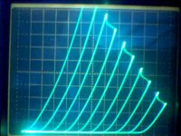
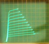
Here is an enhancement mode Mosfet, FQP2N90, with 30 Ohms in the source lead, configured with the same Schade setup as before. (100 K Fdbk R with 20 uF series cap, 22K grid/gate drive R) It has a protection Zener across gate to source and a gate stopper R in front of that, which may be conducting slightly on the leftmost curve, affecting its slope a little.
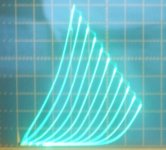
2nd pic is a similarly Schaded Mosfet with a damper rectifier tube in series with the source lead.
By the way, not all damper rectifiers work this smoothly, many have funny irregularities in their conduction curves (not shown on the datasheets either), I had to select the tube for this beauty.
The more consistently clean damper/diode tubes are ones with a filament, rather than an indirectly heated cathode. Although this particular tube was a selected indirectly heated one (better current capability). I do wonder if the usual indirectly heated cathode tubes (triode, pentode) have similar emission irregularities. I have "cured" some badly curved dampers by overheating the heater for a short while. Maybe that is what "burn-in" does for other tubes.
I think if I were making an OTL amp I would use these "triodes".
Here is an enhancement mode Mosfet, FQP2N90, with 30 Ohms in the source lead, configured with the same Schade setup as before. (100 K Fdbk R with 20 uF series cap, 22K grid/gate drive R) It has a protection Zener across gate to source and a gate stopper R in front of that, which may be conducting slightly on the leftmost curve, affecting its slope a little.
2nd pic is a similarly Schaded Mosfet with a damper rectifier tube in series with the source lead.
By the way, not all damper rectifiers work this smoothly, many have funny irregularities in their conduction curves (not shown on the datasheets either), I had to select the tube for this beauty.
The more consistently clean damper/diode tubes are ones with a filament, rather than an indirectly heated cathode. Although this particular tube was a selected indirectly heated one (better current capability). I do wonder if the usual indirectly heated cathode tubes (triode, pentode) have similar emission irregularities. I have "cured" some badly curved dampers by overheating the heater for a short while. Maybe that is what "burn-in" does for other tubes.
I think if I were making an OTL amp I would use these "triodes".
Attachments
Last edited:
The 1st pic above was using 50 mA/div Vert., and 20V/div Horiz.?? (Hmmm, maybe not, the slope of the peaks is different from the presently attached curves)
The 2nd pic above was from several years ago, using a different Mosfet, so I'm not sure what the scaling was then. At least 50 mA/div Vert. I would say. I do recall that the damper tube used there was a 6CG3, which can handle substantial current.
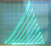
Attached here, is the FQP2N90 Mosfet again in Schade mode (50 mA/div V, 20V/div H), with a 6BY5 damper tube (single section) in the Source lead, NON selected. This is typically what you get if you just pull a damper tube out of the box. Note the "curvy" curves. The majority of damper tubes I've tried (several tube types) have the same kind of "bump" in the curve at moderate current. Over-heating the heater for a while can often fix this or at least improve it some.
I wonder what it would sound like? And do other indirectly heated new tubes (triodes, pentodes) typically have this same sort of conductance curve out of the box? Which maybe straightens out after some burn-in.
The 2nd pic above was from several years ago, using a different Mosfet, so I'm not sure what the scaling was then. At least 50 mA/div Vert. I would say. I do recall that the damper tube used there was a 6CG3, which can handle substantial current.
Attached here, is the FQP2N90 Mosfet again in Schade mode (50 mA/div V, 20V/div H), with a 6BY5 damper tube (single section) in the Source lead, NON selected. This is typically what you get if you just pull a damper tube out of the box. Note the "curvy" curves. The majority of damper tubes I've tried (several tube types) have the same kind of "bump" in the curve at moderate current. Over-heating the heater for a while can often fix this or at least improve it some.
I wonder what it would sound like? And do other indirectly heated new tubes (triodes, pentodes) typically have this same sort of conductance curve out of the box? Which maybe straightens out after some burn-in.
Attachments
Last edited:
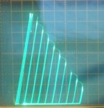
Here is a random 6DQ3 damper with the FQP2N90 in Schade mode. Not too bad, but some slight extra waviness in the curves. 50 mA/div V, 50 V/div H
I bought a box of 150 each of 6CD3/6CE3/6CG3 and 6DQ3/6DU3/6DT3 ($0.35 each) back when they were on sale a few years ago. Somewhere in there are probably some nice ones for Schade Mosfet degenerators.
300B eaters.
Hard to beat those darn $0.05 resistors though.
I wonder what a long string of LEDs would look like. I guess those are exponential.
One could put a 3rd resistor in the Schade R network, from gate to source, to lower the Mosfet gm by dividing the gate drive voltage, that should present a nice (obvious) square law curve then.
Attachments
Last edited:
Well, now that the big secret is out today:
Is this ET? Mystery of strange radio bursts from space - space - 31 March 2015 - New Scientist
Let's take a look at how advanced civilizations might configure their Schaded Tube Output stages:
(all 50 mA/div Vert. and 50 V/div Horiz. except where otherwise noted.)
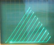
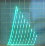
1)21HB5 with g2 drive
2) 21HB5 with Schaded g2 drive (20 mA/div Vert.)
Looks like some compression toward higher g2 voltage (left side), might be from the 120 Ohm g2 stopper R
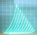
3) 21HB5 with g2 drive and Schading to g1 (20 mA/div Vert)
Looks like some rollover in the curves. Similar to what happens in real triodes, where the feedback and drive are on separate electrodes with different power laws.
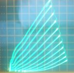
4) 21HB5 with g1 Schade and drive, with g2 also driven without Schading
Looks like usual g1 Schade mode, except its got more gm or gain (Mu) than regular Schade (next up)
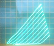
5) 21HB5 with the usual g1 Schade and drive
(Old reliable)
Is this ET? Mystery of strange radio bursts from space - space - 31 March 2015 - New Scientist
Let's take a look at how advanced civilizations might configure their Schaded Tube Output stages:
(all 50 mA/div Vert. and 50 V/div Horiz. except where otherwise noted.)
1)21HB5 with g2 drive
2) 21HB5 with Schaded g2 drive (20 mA/div Vert.)
Looks like some compression toward higher g2 voltage (left side), might be from the 120 Ohm g2 stopper R
3) 21HB5 with g2 drive and Schading to g1 (20 mA/div Vert)
Looks like some rollover in the curves. Similar to what happens in real triodes, where the feedback and drive are on separate electrodes with different power laws.
4) 21HB5 with g1 Schade and drive, with g2 also driven without Schading
Looks like usual g1 Schade mode, except its got more gm or gain (Mu) than regular Schade (next up)
5) 21HB5 with the usual g1 Schade and drive
(Old reliable)
Attachments
Last edited:
- Status
- This old topic is closed. If you want to reopen this topic, contact a moderator using the "Report Post" button.
- Home
- Amplifiers
- Tubes / Valves
- Schade and CFB exactly equivalent