I am using the 8 version. My design axis is at the height of the tweeter - my stands are 25" tall. Of course that means the tweeter is off-axis about 14 degrees due to baffle tilt. I found this to be fine since the TW29 has a rsing top octave anyway.
It's interesting to see that the 8 Ohm version seems to have a deeper suck-out at the edge resonance than the 4 Ohm version, even though the difference isn't huge.
My phase response is measured from the spike of the impluse of the MLS with excess phase removed for time of flight. At other distances it will pretty much look the same, as it will follow the frequency response. In other words if you move off axis, or get far enough away that the top end is dropping then this will be reflected in the phase response as well. Phase and frequency response are intimately tied together in this type of crossover, hence the term "minimum phase response".
Sorry, I didn't read your post carefully enough.
/Göran
I don't know if this will be of interest or not, but here is an article I wrote explaining how to determine the relative acoustic offsets between two drivers using simple frequency response measurements and a crossover simulation program. In this version you simply assign the tweeter's acoustic center to be the reference point, even though its exact location may be unknown. Then using this method you can very precisely determine the offset distance between the reference point and the woofer's acoustic center.
As you know, the location of the acoustic center of a driver is not always obvious. For example, for many years it was regard to be the position of the voice coil, so if voice coils were aligned then we had time alignment. Later research found this to not be correct. In most midwoofers the acoustic center is actually very close to the attachment point of the coil former and cone, sometimes, depending on the driver design and how the dust cap is implemented, it can even be forward of this. With dome tweeters it is typically close to the base of the dome.
This method can very easily be used to determing how to offset drivers to exact time alignment and it easier to dial in and read than by viewing the impulse and step response.
Here is a link to a pdf file with the article in it:
https://www.box.com/s/ouxjjsx0m8bs00cil5iq
Jeff B.
Yes, I've bee using this method for years. It's fast, simple and accurate.
")
I'm using LspCAD 6 Pro for simulation and design and it's very easy to import it in LspCAD and determine the off-set and it's easy to recalculate for different distances etc.
Here's another article using the same method Finding Relative Acoustic Offsets Empirically
Regards
/Göran
The acoustic center can be found by eroding the frequency response.
Do a Hilbert transform of the transfer function. Calculate the excess phase and then the
excess group delay. The amount of delay that is necessary to make the excess group delay flat gives the acoustic center.
Anyway in practical terms that does not mean much. A real transducer seldom has a dead flat response and there will also be some all pass terms in the area where the driver breaks up in partial resonances. Richard Heyser made a point that the acoustic center can also move with frequency.
I have now measured the drivers in the test cabinet and found that the acoustic centers match well when i measure on the tweet axis at ca. 1m.
The woofer sits on a baffle that is 38mm thicker then the tweeter baffle.
The crossover i made is a L/R second order with the tweeter reversed.
The acoustic phase responses match very well.
The acoustic center can be found by eroding the frequency response.
Do a Hilbert transform of the transfer function. Calculate the excess phase and then the
excess group delay. The amount of delay that is necessary to make the excess group delay flat gives the acoustic center.
Anyway in practical terms that does not mean much. A real transducer seldom has a dead flat response and there will also be some all pass terms in the area where the driver breaks up in partial resonances. Richard Heyser made a point that the acoustic center can also move with frequency.
I have now measured the drivers in the test cabinet and found that the acoustic centers match well when i measure on the tweet axis at ca. 1m.
The woofer sits on a baffle that is 38mm thicker then the tweeter baffle.
The crossover i made is a L/R second order with the tweeter reversed.
The acoustic phase responses match very well.
My sloped baffle results in setting the tweeter back 37.5mm, so we are very close on this.
Cool, i had some 19mm thick chipboard so 2 x 19 = 38.
That is a tiny bit more then the calculated 32 mm but on the tweeter axis in the near field,
say not more then 2m away the woofer is a bit further away because of geometry.
Anyway, i will try to simulate your solution too. I will not copy it though without your permission.
That is a tiny bit more then the calculated 32 mm but on the tweeter axis in the near field,
say not more then 2m away the woofer is a bit further away because of geometry.
Anyway, i will try to simulate your solution too. I will not copy it though without your permission.
Here is a first attempt at a crossover. It is an L/R2, the lowest order crossover that has the drivers in phase so the lobing is symmetrical in the vertical direction. It also has less phase distortion then an L/R 4 although in the Step Response you can see that the tweeter starts negative.
The ETC shows that this design storers very little energy.
More later.
The ETC shows that this design storers very little energy.
More later.
Attachments
-
Satori Monitor prot L-R2 HT crossover.pdf9.6 KB · Views: 1,028
-
Satori Monitor prot L-R2 frd.pdf17 KB · Views: 441
-
Satori Monitor prot L-R2 HT plus frd.pdf17.1 KB · Views: 326
-
Satori Monitor prot L-R2 individual phase.pdf12.8 KB · Views: 270
-
Satori Monitor prot L-R2 group delay.pdf14 KB · Views: 260
-
Satori Monitor prot L-R2 impedance.pdf14.4 KB · Views: 280
-
Satori Monitor prot L-R2 step.pdf11.9 KB · Views: 335
-
Satori Monitor prot L-R2 etc.pdf11.4 KB · Views: 375
-
Satori Monitor prot L-R2 TT crossover.pdf9.5 KB · Views: 701
Here you can see the effect of the edge between tweeter and woofer.
When it is not chamfered there is a suck out that amounts to 5dB in a certain range.
When it is not chamfered there is a suck out that amounts to 5dB in a certain range.
Attachments
Why is it preferable to design with tweeter at ear height rather than midway between woofer and tweeter? Thanks
Thanks for posting links to acoustic center articles.
The crossover looks very good!
I am not sure who the question was directed to, so I will chime in, and anyone else is welcome to as well.
However, the tweeter axis is typically used as the design and listening axis simply because it is the more directional of the two drivers, especially at the upper end of its frequency range. Midwoofers are usually crossed over before they become directional, but we don't have that luxury with tweeters. If a tweeter is large, like these 29mm SB tweeters then the top octave can roll-off quickly as you move off axis.
Jeff
Still i would like to see the Step Response.
Thanks for explaining though.
I found these snapshots from back in April. They aren't very high resolution so I hope they are worth something. Here's the Step Response on the speaker (It says Impulse, but it's actually a Step Response):
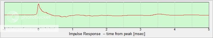
And here's the Impulse Response on the design axis:
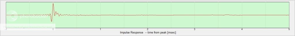
Jeff
However, the tweeter axis is typically used as the design and listening axis simply because it is the more directional of the two drivers, especially at the upper end of its frequency range. Midwoofers are usually crossed over before they become directional, but we don't have that luxury with tweeters. If a tweeter is large, like these 29mm SB tweeters then the top octave can roll-off quickly as you move off axis.
Jeff
Thanks Jeff, that makes sense. So tilting the baffle works as HF EQ as well as driver alignment. Joachim has the tweeter firing horizontally, but you have chosen tilt. Should there be much attenuation of tweeter at HF with this amount of tilt?
Thanks Jeff, that makes sense. So tilting the baffle works as HF EQ as well as driver alignment. Joachim has the tweeter firing horizontally, but you have chosen tilt. Should there be much attenuation of tweeter at HF with this amount of tilt?
Not much, it's only 14 degrees. I posted the measured response a few posts up so you can see there's no droop in the top octave at this angle. In reality if I raise the mic and angle it at the tweeter the response would be rising a bit more above 12khz, so the angle does help to flatten the forward radiating energy a tiny bit.
Here's another pic. Only this one shows the old one-piece face plate on the tweeter, but it gives a good idea of the speaker's look.
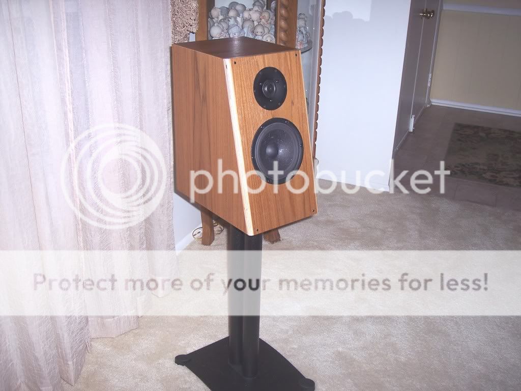
Jeff B.
Jeff,
What's your baffle dimension (baffle width and baffle edge round-over)?
I'm a bit curious because, when I started some simple quick and dirty cross-over simulations based on these measurements I found out that the baffle step where a bit more complicated than usual to take care of, at least when I simulated LR2 filter with 3kHz x-over point and didn't want an excessive amount of components. If I lower the x-over point to about 2.4kHz it looks easier.
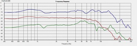
When I measured my Satori mid-woofer I used an 24.8cm wide baffle with (r=18mm) round-over for the baffle edges and get a broad hump (+5dB) centered at approximately 800Hz and f/2 at 570 and 1150Hz.
For comparison:
Measured @ Tweeter-axis, on-axis.
Blue = Satori MW16P-4 (24,8cm baffle, r=18mm round-over)
Red = ScanSpeak Revelator 15W/4531G00 (21,6cm baffle, r=12mm round-over)
Green = AudioTechnology 15H520613SDK (21,6cm baffle, r=12mm round-over)
Happy New Year!

/Göran
Attachments
Jeff,
What's your baffle dimension (baffle width and baffle edge round-over)?
I'm a bit curious because, when I started some simple quick and dirty cross-over simulations based on these measurements I found out that the baffle step where a bit more complicated than usual to take care of, at least when I simulated LR2 filter with 3kHz x-over point and didn't want an excessive amount of components. If I lower the x-over point to about 2.4kHz it looks easier.
When I measured my Satori mid-woofer I used an 24.8cm wide baffle with (r=18mm) round-over for the baffle edges and get a broad hump (+5dB) centered at approximately 800Hz and f/2 at 570 and 1150Hz.
For comparison:
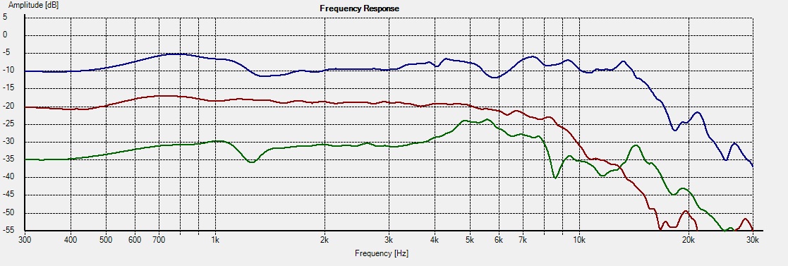
Measured @ Tweeter-axis, on-axis.
Blue = Satori MW16P-4 (24,8cm baffle, r=18mm round-over)
Red = ScanSpeak Revelator 15W/4531G00 (21,6cm baffle, r=12mm round-over)
Green = AudioTechnology 15H520613SDK (21,6cm baffle, r=12mm round-over)
Happy New Year!
/Göran
My baffle is 16" tall by 9" wide with 3/4" roundover (40.6 cm x 22.9 cm, 18mm roundover)
I did not find the baffle step to be troublesome at all. However, you will find with a driver like this on this size baffle that the simplest crossover will typically net a crossover point close to 2 kHz or over lower.
I never force a crossover (meaning pick the crossover point in advance and try to force that to be my crossover point). You will find that depending on the woofer and tweeter's natural response, their phase response, and the offset between the drivers, that with certain acoustic slopes there is a natural crossover point that you can arrive at with very simple electrical circuits and achieve the correct phase alignment at the same time. In my case the crossover in my Kairos speaker is a hair under 2 khz (about 1.9kHz, but slopes are gradual in this region).
If I tried a higher crossover point, like 3khz, which I experimented with, then the circuits picked up considerably more elements.
And remember, crossover types like LR2 or LR4 are always a combination of the driver's natural roll-off and the circuit's transfer function. In other words, for an LR4 crossover, if the tweeter is begining to roll-off naturally second order around 1-2 kHz then all you may need is a second order circuit to achieve a perfect LR4 response.
And of course, if the drivers are on a flat baffle, then asymmetrical roll-offs are usually required to compensate for the relative offset of acoustic centers and arrive at good phase tracking (within the crosover region).
Jeff
My baffle is 16" tall by 9" wide with 3/4" roundover (40.6 cm x 22.9 cm, 18mm roundover)
Thanks for the info!
I did not find the baffle step to be troublesome at all. However, you will find with a driver like this on this size baffle that the simplest crossover will typically net a crossover point close to 2 kHz or over lower.
I never force a crossover (meaning pick the crossover point in advance and try to force that to be my crossover point). You will find that depending on the woofer and tweeter's natural response, their phase response, and the offset between the drivers, that with certain acoustic slopes there is a natural crossover point that you can arrive at with very simple electrical circuits and achieve the correct phase alignment at the same time. In my case the crossover in my Kairos speaker is a hair under 2 khz (about 1.9kHz, but slopes are gradual in this region).
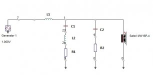
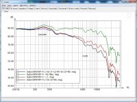
Complicated was perhaps a strong word, I would say a bit tricky since I were hoping not to need to equalizing the remaining hump with a LCR circuit (L2+C1+R1), but again this is purely experimental at this stage. See picture 2 and 3.
If I tried a higher crossover point, like 3khz, which I experimented with, then the circuits picked up considerably more elements.
And remember, crossover types like LR2 or LR4 are always a combination of the driver's natural roll-off and the circuit's transfer function. In other words, for an LR4 crossover, if the tweeter is begining to roll-off naturally second order around 1-2 kHz then all you may need is a second order circuit to achieve a perfect LR4 response.
And of course, if the drivers are on a flat baffle, then asymmetrical roll-offs are usually required to compensate for the relative offset of acoustic centers and arrive at good phase tracking (within the crosover region).
I haven’t yet finally decided which tweeter to use in combination with the Satori mid-woofer, but I’ve tested a couple of ScanSpeak tweeters on the same baffle, hence the experimental 2.4kHz x-over which seems viable with one of them using a stepped baffle and yes, all your advices is a nice good sum-up of things among others to consider in the chosen design.
Picture 2: Experimental 2.4kHz LR2 x-over
Picture 3: Mid-woofer 15deg off-axis, effect of LCR
Sorry Joachim it wasn’t my intention to hijack your thread, but I was a bit curious and thought it was interesting to compare the different baffle dimensions we used, yours 30cm wide baffle and Jeffs 22.9cm and my 24.8cm.
/Göran
Attachments
Göran, do not worry, your experiments are interesting and helpful.
Jeff, great work you did.
I placed the crossover at ca.2.1kHz. Yes it seems to be that lower crossover points work better with the Satori Mid-Woofer. I prefer lower crossover points anyway to stay out of the problem zone in the upper range.
The Satori is very extended but does not work as a perfect piston any more higher up.
Fortunately modern tweeters are quite extended in the deeper regions too.
Yes, the DIY version of the cabinet i designed has a straight baffle with the woofer on a thinker baffle but the professionally made cabinets made by SB will have an angled baffled, not much different then Jeffs design. I posted a rendering of that version some time ago.
And remember, crossover types like LR2 or LR4 are always a combination of the driver's natural roll-off and the circuit's transfer function. In other words, for an LR4 crossover, if the tweeter is begining to roll-off naturally second order around 1-2 kHz then all you may need is a second order circuit to achieve a perfect LR4 response.
I understand what you are saying, you are looking at the amplitude slopes, shaping them as would LR4 electrical filters acting on drivers with no rolloff.
But true LR crossovers also have coherent phase between the crossed drivers. If you replace half the electrical filter with acoustic rolloff don't you lose that phase coherency? A 4th order electrical filter twists the phase faster than 2nd order electrical. I can understand that the rising inductance of the woofer coil adds some phase in the right direction, but does it change fast enough to match an electrical 4th order filter? I understand the low end roll off of the tweeter to be caused by decreasing acoustic impedance which I think will not affect its phase at all, but resonance affects phase. So is it really a true Linkwitz-Riley 4 crossover since phase is not necessarily coherent all the way through the filter band? Or is it?
I see this point made occasionally, that acoustic slope is what matters, but I never had opportunity to ask for clarification about phase until now. It is rare to have accomplished designers willing to share their expertise as you guys are here. Thanks!
Rich
Yes, it is the acoustic response that matters. That has the consequence that the crossover schematic does not look like a textbook example at all.
I have made L/R4 and L/R2 filters many times where the phase matched over a very wide range. I do that usually with LSP-CAD and do the rest by trimming with hand while watching the individual phase window.
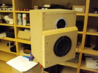
Here is a picture how the prototype box looks at the moment. I will round the edges and sink in the drivers. After this i will fine tune the crossover.
When the factory made cabinets come i will have to fine tune again.
While Jeff has made a phase linear version and Göran is working on an L/R4 i will stick to the L/R2. We have a lot of options then.
I have made L/R4 and L/R2 filters many times where the phase matched over a very wide range. I do that usually with LSP-CAD and do the rest by trimming with hand while watching the individual phase window.
Here is a picture how the prototype box looks at the moment. I will round the edges and sink in the drivers. After this i will fine tune the crossover.
When the factory made cabinets come i will have to fine tune again.
While Jeff has made a phase linear version and Göran is working on an L/R4 i will stick to the L/R2. We have a lot of options then.
Attachments
- Home
- Vendor's Bazaar
- SB Acoustics Satori Monitor