These transistors
What I was trying to determine was whether the output transistors of the pair were being turned on or not and whether all behaved the same. That measurment is the collector voltage of Q004/5 and 6.
I don't understand this. Are you saying my measurements were done wrong?
Might have to stop for the day.
Thanks again for your help and patience.
kffern
I think you measured 4.9v across the zener earlier and so that would seem to be in order.
0.66 volts across the 6.8 ohm/s sounds more reasonable being a current of 300ma or so.
Could the 19 volt zener be bad and giving just 16 volts ? Quick answer is yes, more detailed answer is that I suspect it is probably all right in this case.
I think the 19 volts is low simply because of the current being drawn in the units present faulty state. The simple one transistor regulator has limited ability both in itself and in the small mains transformer feeding the unit. It just can't support more current and so all the voltages fall a little.
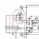
The base to collector voltage doesn't really tell us much in this case. What is more useful is knowing the collector voltage with respect to ground. for Q004/5/6
I would expect all three to be similar in this faulty state.
If we then apply the short circuit I mentioned before to Q008 (linking E and C) then that should turn all those drive transistors off and the collector voltage on them should rise. At this point (and assuming the circuit behaves in this way) then I think you would find the 19 volts comes back up.
Everything at this stage is gathering evidence as to what the problem may be, and we are working on the assumption that the fault isn't in one of the 'non repairable' parts such as the windings or the little transformer L001.
There is still much to check if we still don't get any clues at this point.
0.66 volts across the 6.8 ohm/s sounds more reasonable being a current of 300ma or so.
Could the 19 volt zener be bad and giving just 16 volts ? Quick answer is yes, more detailed answer is that I suspect it is probably all right in this case.
I think the 19 volts is low simply because of the current being drawn in the units present faulty state. The simple one transistor regulator has limited ability both in itself and in the small mains transformer feeding the unit. It just can't support more current and so all the voltages fall a little.
The base to collector voltage doesn't really tell us much in this case. What is more useful is knowing the collector voltage with respect to ground. for Q004/5/6
I would expect all three to be similar in this faulty state.
If we then apply the short circuit I mentioned before to Q008 (linking E and C) then that should turn all those drive transistors off and the collector voltage on them should rise. At this point (and assuming the circuit behaves in this way) then I think you would find the 19 volts comes back up.
Everything at this stage is gathering evidence as to what the problem may be, and we are working on the assumption that the fault isn't in one of the 'non repairable' parts such as the windings or the little transformer L001.
There is still much to check if we still don't get any clues at this point.
I get 16V for Q005 and Q006 but only 2.2 for Q004.The base to collector voltage doesn't really tell us much in this case. What is more useful is knowing the collector voltage with respect to ground. for Q004/5/6.
I would expect all three to be similar in this faulty state.
Finally managed this as I was a bit nervous about shorting unnecessary bits.If we then apply the short circuit I mentioned before to Q008 (linking E and C) then that should turn all those drive transistors off and the collector voltage on them should rise. At this point (and assuming the circuit behaves in this way) then I think you would find the 19 volts comes back up.
 Had to think about it for a while.
All the voltages went to 18.4v. Hope this helps.
BTW if I get this working its going to my hipster nephew who has a record collection but never owned a turntable!!
Regards,
kffern
Last edited:
It might help... lets pursue this. Also I'm guessing you haven't an ocilloscope ?
Here is what I'm thinking.
Q004 readings are the odd one out. That transistor appears to be on and conducting while the other two are off. That seems odd because all three stages are identical and as far as static DC readings go I would expect them all to be similar.
The temporary short appears to show that Q004 is able to turn off when forced (and so isn't short or totally non operational).
Q001 must be on in order to turn on Q004.
It is worth checking both Q001 and D001.
If you isolate D001 then that should turn off Q001 and allow the voltage on Q004 collector to rise. Assuming that happens then you can check D001 out of circuit. Make 100% certain there is no reverse leakage when tested using a high ohms range on the meter. The diode test function is no good for leakage, use the high ohms range. Forward biased and it should read like a normal diode (on the diode range).
Remember to remove that temporary short from earlier.
Hi Mooly,
Lifted the end of D001 where it joins Q001 base. on power up C on Q004 shows 16V.
D001 tests fine with the diode test fn. When forward biased I get 0.58v and nothing reversed.
Trying the resistivity tests seems a problem as I get OL both ways. I checked on a couple of spare 04007 I had and get the same result. I am using one of these
http://www.altronics.com.au/p/q1070-20-range-true-rms-digital-multimeter/#fancy-inner
Regards,
kffern
Last edited:
It seems the diode is OK at a basic level.
Your meter sounds like it tests resistance at a really low voltage level, which is good in some ways and not in others. The old AVO8 for example uses a 15 volt test voltage which will show leaky devices in an instant, but on the other hand you don't always want to apply 15 volt across some of todays sensitive devices.
Lifting the diode shows the two transistors responding as expected.
If we have any doubt on the diode then just tag a 4007 in its place to eliminate all doubt.
We need to look further around this little area of circuitry to see why Q001 is being turned on.
The only way this can happen is if Q001 base gets pulled down to a lower voltage than the emitter and that can only be done via R004 and R001. There is also one of the windings connected to the junction of those resistors.
Is it possible there could be a short on the winding NS201 to ground ?
The next measurements have to be with everything back in place and to compare the voltages at the junction of those resistors with the other two sets (R005/002 and R006/003)
If its easily identifiable then you could also try unsoldering the lead to NS201 which is marked as terminal 2 on the diagram.
You mentioned at the start that the caps looked 'brand new'.
Is there any possibility this could have been worked on before ? In particular, any chance of the windings have been unsoldered and reattached in a wrong order.
The motor hood hadn't been been removed as the tiny screws still had the green paint on them which was unbroken. Someone had looked at the PS section probably to check the fuse. One screw wasnt done up properly.You mentioned at the start that the caps looked 'brand new'.
Is there any possibility this could have been worked on before ? In particular, any chance of the windings have been unsoldered and reattached in a wrong order.
By brand new I meant original. They were all Elna caps and the old larger sizes. I had to go up a couple of Voltage ratings to get close to the lead spacing.
I did think of lifting the leads to the motor. I measured them earlier and got low v for 1 and 2. I noted the colours.
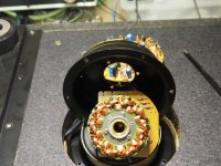
I had a quick look at the coils when I pulled out the spindle and didn't notice any burnt or damaged areas. I could look again.
Will update shortly.
Regards,
kffern
OK 
What we are really trying to determine at this point is why Q001 is apparently on, while Q002 and Q003 are off. All three seem to share a similar arrangement of parts around them, and all three even share the same emitter connection. So under static conditions you would think all three should be giving similar voltage readings.
The three coils NS201, 202 and 203 also share a common feed.
Don't discount the possibility of resistors being faulty. It occasionally happens. R001 would be worth looking at.
A resistance check of those three windings would also be useful, just to see if there were any differences.
Check resistance from points 2, 4 and 6 to ground. Keep the meter leads the same way around for consistency (the test voltage from the meter can give different results as interacts with the circuitry if you swap them around. So just be consistent). Is point 2 reading lower to ground than the other two ?
Voltages R004/R001 - 13.9v (point 2)The next measurements have to be with everything back in place and to compare the voltages at the junction of those resistors with the other two sets (R005/002 and R006/003).
R005/R002 - 13.7v (point 4)
R006/R003 - 13.7v (point 6)
I checked voltages at point1 - 2.2v
point 3 - 15.7v
point 5 - 15.7v
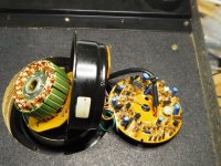
D201 x 3 are under another cover below the circular board secured by 3 screws.
Let me know if I need to. The 2.2v should say something. I would have thought that if a coil was shorting it should show up on 3 others as well?
Regards,
kffern
Voltages R004/R001 - 13.9v (point 2)
R005/R002 - 13.7v (point 4)
R006/R003 - 13.7v (point 6)
I checked voltages at point1 - 2.2v
point 3 - 15.7v
point 5 - 15.7v
D201 x 3 are under another cover below the circular board secured by 3 screws.
Let me know if I need to. The 2.2v should say something. I would have thought that if a coil was shorting it should show up on 3 others as well?
Regards,
kffern
Very interesting.
Point 1 is low, re-confirming that that pair of transistors is conducting.
Point 2 is actually slightly high compared to the others. That's totally unexpected. A higher DC voltage at this point should be turning Q001 off (with it being a PNP type).
That result blows my train of thought out of the water at this point.
We have to ask now whether the circuit is actually trying to run and whether there is an AC component present and superimposed on those voltages.
Carry on with the tests I mentioned in my previous post and check those three diodes.
If you move the platter say a third of a turn round, does the different voltage reading we are seeing change ?
Checked R001, 004, 007and 017 are spot on.Don't discount the possibility of resistors being faulty. It occasionally happens. R001 would be worth looking at.
I can't read anything here. I tried a few different grounds but still nothing.Check resistance from points 2, 4 and 6 to ground.
Regards,
kffern
The diodes look OK. Measurements across each are the same. I don't think I will be able to lift them without changing them out as there is very little lead wire to play with and they are very thin.[/QUOTE]Definitely look at those three diodes.
No. all the same as before.Also, does anything voltage wise change as you operate the speed selector and controls ?
The wire on one of the coils is a bit loose and a loop sticks up. I pulled it lightly and it seems to be connected but that is a worry. If I unsoldered the stator(?) to do a continuity check I'm not sure I will be able to get it back together again.
Might have to knock off for the night.
Regards,
Kffern
- Status
- This old topic is closed. If you want to reopen this topic, contact a moderator using the "Report Post" button.
- Home
- Source & Line
- Analogue Source
- Sansui SR525 doesn't turn