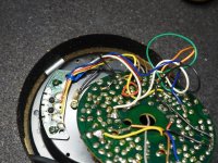
Those three diodes might be checkable in circuit. If you could isolate the wire marked GY then they could be checked as a group for leakage. With the red meter lead on any of the diodes cathode (striped end) then there should be no reading to any of the anodes. Use a high ohms range. That would test all three in one go for leakage as they would just appear as a parallel set of three.
Hi Mooly,Those three diodes might be checkable in circuit. If you could isolate the wire marked GY then they could be checked as a group for leakage. With the red meter lead on any of the diodes cathode (striped end) then there should be no reading to any of the anodes. Use a high ohms range. That would test all three in one go for leakage as they would just appear as a parallel set of three.
Isolated and checked the diodes with the diode fn on my DMM. All look good under forward bias with 0.6v. Hope you have come up with some good ideas.
Thanks,
Kffern
I mentioned 'oscilloscopes' a couple of times. You haven't got one I assume ? If I had this in front of me I would do a check of the oscillator and drive stages and see dynamically what was happening and if there were an AC component present.
So we have not got very far although we have logically proved much.
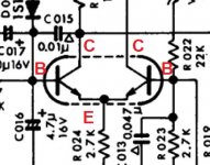
Lets do a voltage check of the oscillator and see if anything stands out. That is Q009 which is a dual transistor.
What is on E and then C and B for left and right sides. So five readings.
Do you see the small caps C1, 14 and 15 that are marked with a small triangle. Those are indicated in the service manual to be ceramic types and so are probably the small 'compressed disc' type. Those types have a reputation for going leaky and the only way to prove a slight leak is to unsolder one end and do an ohms check on a high range on the meter. Even then, given the low test voltage of the meter the result may be inconclusive but definitely worth trying.
Also, I have kept assuming there is an issue around Q001 and Q004 with those being the odd ones out of the set... I'm just thinking on that Still valid reasoning, however...
We proved the transistors were able to switch OK but did we check D004 ? A faulty D004 may not affect the result of the static tests we have done but would affect the dynamic AC performance of the circuit. Worth checking. Lift one end and check for being leaky.
So we have not got very far
although we have logically proved much.Lets do a voltage check of the oscillator and see if anything stands out. That is Q009 which is a dual transistor.
What is on E and then C and B for left and right sides. So five readings.
Do you see the small caps C1, 14 and 15 that are marked with a small triangle. Those are indicated in the service manual to be ceramic types and so are probably the small 'compressed disc' type. Those types have a reputation for going leaky and the only way to prove a slight leak is to unsolder one end and do an ohms check on a high range on the meter. Even then, given the low test voltage of the meter the result may be inconclusive but definitely worth trying.
Also, I have kept assuming there is an issue around Q001 and Q004 with those being the odd ones out of the set... I'm just thinking on that
Still valid reasoning, however...We proved the transistors were able to switch OK but did we check D004 ? A faulty D004 may not affect the result of the static tests we have done but would affect the dynamic AC performance of the circuit. Worth checking. Lift one end and check for being leaky.
No oscilloscope. The guy I was goinng to ask has gone away for a while. I might buy one of those $25 ones from ebay but that will be a while too.I mentioned 'oscilloscopes' a couple of times. You haven't got one I assume ? If I had this in front of me I would do a check of the oscillator and drive stages and see dynamically what was happening and if there were an AC component present.
1(B) - 0.47v, 2(E) - -0.05, 3(C) - -0.01v, 4(E) - 4.95v, 5(B) - 0.48vLets do a voltage check of the oscillator and see if anything stands out. That is Q009 which is a dual transistor.
I tried lifting one but looks like I have nicked the case. I will buy new ones tomorrow and replace them. That would be easier and more reliable. They are just too close together. By the time I put them back they will surely be damaged. Its a good couple of km walk during lunch break too.Do you see the small caps C1, 14 and 15 that are marked with a small triangle.
Checked out good with diode test on DMM.We proved the transistors were able to switch OK but did we check D004 ?
Thanks,
kffern
Hmmm
The emitter is the common terminal here, but I think I can figure them out. The readings are a bit inconclusive tbh, meaning I can't say for sure if there is a problem there or not.
Lets see what the cap check brings. C014 is actually across the -5v rail and so isn't really a suspect.
The emitter is the common terminal here, but I think I can figure them out. The readings are a bit inconclusive tbh, meaning I can't say for sure if there is a problem there or not.
Lets see what the cap check brings. C014 is actually across the -5v rail and so isn't really a suspect.
Attachments
I'm not sure if it's any help but the circuit for the SR-535 looks very similar, and there are voltages shown on the cct diagram as well as a description of the functionality.
Sansui SR-535 - Manual - Direct-Drive Turntable - Vinyl Engine
Sansui SR-535 - Manual - Direct-Drive Turntable - Vinyl Engine
Hi Mooly,
I changed C001. I managed to push out R011 by mistake as they were so close together. Pushed it back but couldn't seem to measure any resistance with it installed so will replace tomorrow. They didn't have stock of the 0.01uF C015 today but will try another branch tomorrow.
I will recheck voltages tomorrow as well.
Regards,
kffern
Thanks for finding the 535 manual Ralph.
OK
I was reading the circuit description earlier and it goes some way to explaining the higher frequency oscillator at the right (Q007). This is really where a scope comes into its own in allowing us to see if its running.
Another random thought was that the odd but stable readings on Q001 and Q004 could actually be because that stage is working and there is in fact an issue with one of the other sets of drivers that is failing to 'carry on' the rotational sequence. Its a bit hard to explain the reasoning of that simply.
Careful voltage measurements across the B-E junction of those pairs might show an anomaly. You should not see more than around 0.7 volts across the junction when forward biased. That means base positive with respect to emitter for the NPN and vice versa for the PNP.
I'm sorry this must all seem so random to you but we passed the point where something more 'obvious' might have shown.
I was reading the circuit description earlier and it goes some way to explaining the higher frequency oscillator at the right (Q007). This is really where a scope comes into its own in allowing us to see if its running.
Another random thought was that the odd but stable readings on Q001 and Q004 could actually be because that stage is working and there is in fact an issue with one of the other sets of drivers that is failing to 'carry on' the rotational sequence. Its a bit hard to explain the reasoning of that simply.
Careful voltage measurements across the B-E junction of those pairs might show an anomaly. You should not see more than around 0.7 volts across the junction when forward biased. That means base positive with respect to emitter for the NPN and vice versa for the PNP.
I'm sorry this must all seem so random to you
but we passed the point where something more 'obvious' might have shown.I have replaced the resistor, C001 and C015. I know it isn't what you asked but as I was outside I re-checked the voltages on Q001-004.
Now Q001 has E - 13.4; C - 13.4 and B - 12.7v
Q002 and Q003 both have E - 13.2, C - 1.5, B - 12.1v.
I really appreciate you hanging in this far Mooly but I think it might be better for both of us if we wait till I get a scope and start again. Its very hard to reach into the pins and I'm possible doing more harm than good right now. I can't always be sure I have the probe on the correct legs or pads.
Unless you come up with something in the meantime.
Regards,
kffern
Now Q001 has E - 13.4; C - 13.4 and B - 12.7v
Q002 and Q003 both have E - 13.2, C - 1.5, B - 12.1v.
I really appreciate you hanging in this far Mooly
but I think it might be better for both of us if we wait till I get a scope and start again. Its very hard to reach into the pins and I'm possible doing more harm than good right now. I can't always be sure I have the probe on the correct legs or pads.Unless you come up with something in the meantime.
Regards,
kffern
- Status
- This old topic is closed. If you want to reopen this topic, contact a moderator using the "Report Post" button.
- Home
- Source & Line
- Analogue Source
- Sansui SR525 doesn't turn