2x18VAC will heat the input CCS MOSFET more but not noticeably so if you will not jump over a 200mA setting. On the other hand that extra voltage across is lowering the CCS MOSFET's parasitic capacitance (more than 25V isn't doing something really better) provided there is no difficult heat exchange situation.
Just received talema encapsulated 2x15V 160VA after 3 months waiting. I need advice for below questions:
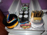
- Currently I'm using 4x 10.000uF off board with speaker cable connecting them to pcb trace. I'm confused now after reading latest comment from salas, should I keep it or changed it with 4x 4.700uF so I can solder them on pcb?
- Will it degrade signal quality if i use socket connector and potensio leg connector instead of direct solder?
Thanks
Attachments
You got to try out the caps in both ways and see what you like best. Its not only the connection its they are different types and value as well.
Solder brings additional security, but proper press fit mechanical connections can be very good too if they feel well designed and tight.
Solder brings additional security, but proper press fit mechanical connections can be very good too if they feel well designed and tight.
The regulator makes a pretty good job of isolating the amplifier/buffer from the changes/interference coming in from the mains.
For that reason one should not expect a good regulator to show a big improvement by improving the quality of the DC coming from the smoothing & rectifier.
An lm317 is a poor regulator especially at HF and this generally shows a big measurable improvement when less ripple is fed to the chip. So big that it is usually audible.
I would not expect that to happen with the DCB1. But the experiment was worthwhile.
RC is a filter.
rC is a filter.
rCRC is a cascaded filter.
The r is the transformer and wiring and rectifier resistance.
The first C is the first smoothing capacitor.
The R is the added resistor between the two capacitors.
The last C is the main supply of transient current to feed changes in current demand.
Andrew T
Thanks for the above clarification. Very much appreciated. I'll take note.
Regards
Scorpion
You got to try out the caps in both ways and see what you like best. Its not only the connection its they are different types and value as well.
Solder brings additional security, but proper press fit mechanical connections can be very good too if they feel well designed and tight.
I think i'll swap those caps with 4.700uF to simplify connection, I'd rather try out different potensio/attenuator (i'm saving extra money for tkd 2P65CS) which resulting me thinking of those connectors. those mechanical connections are so tight

I want to make a regulator to supply intake fan, is it ok to get it supplied from main caps after mur820? hopefully that fan does not create unwanted electrical noise
Hi everyone,
Here is a thread about some resistor tryouts in the Salas hotrodded DCB1...
http://www.diyaudio.com/forums/anal...rodded-dcb1-resistor-tryouts.html#post3837430
Let's have some fun and see what comes out of it ;-)
Regards
Scorpion
Here is a thread about some resistor tryouts in the Salas hotrodded DCB1...
http://www.diyaudio.com/forums/anal...rodded-dcb1-resistor-tryouts.html#post3837430
Let's have some fun and see what comes out of it ;-)
Regards
Scorpion
Too bad that I dpnt have any scope access
Too bad. Attach the fan, don't attach the fan and try determine if you can hear a degradation or not? Can't think of anything simpler procedure if you can't "see" what it does with an instrument.
Hi everyone,
Here is a thread about some resistor tryouts in the Salas hotrodded DCB1...
http://www.diyaudio.com/forums/anal...rodded-dcb1-resistor-tryouts.html#post3837430
Let's have some fun and see what comes out of it ;-)
Regards
Scorpion
Wishing you it will stay just a "fun" thread.
Yep !!!
Can already imagine believers vs nonbelievers starting a guerilla over the difference in sound (or lack of) between different types and brands.
Measures and science vs what one's hears detect or how he feels (can it really be measured ?) while experimenting. Already expecting the "biased" stuff popping up...
I will post my findings no matter what. And some pics as well.
If there are audible differences, ok. If not, so be it.
Regards
Scorpion
Thank youNot a problem. Its just 10V there across each of those caps.
I'm trying to figure out if my trafo is enough or not.
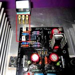
At the moment I have 16.5V after rectifiers. Regulated out is 10.4.
I measured 2.1V on the resistors (11 ohm) and about 3.8V on the IRF.
So I'm not really sure if this will be enought or I should get a bigger trafo? Or short circuit 1 LED and get about 8.5V reg out?
The absolute minimum is the regout+IRF+res voltages?
- Home
- Source & Line
- Analog Line Level
- Salas hotrodded blue DCB1 build