Merry Christmas to you all
Today I got a new multimeter, and I have checked my 2SK163, the IDSS is arround 8.22mA ~8.34 mA. Surprisingly, I have 4pcs exact 8.24mA. Is it good JFET for DCB1 ?
Sorry for beginner question, I guess the functionality of the relay in Hypnotize board is only for power on delay, is it works for DC protection? What is the benefit of relay circuit in DCB1?
My amplifier have already capacitor 1uF in input section. Do you think it is enough for speaker DC protection without using the relay in DCB1?


Yes the IDSS is OK for that NEC JFET and DCB1. What DMM you got in the end?
The relay is to not let any small thump pass when powering on, but mainly not to let a few seconds long up to 2V DC cycle pass when powering off as the electrolytics drain out in the symmetric supplies in no voltage lock and timing.
When your every power amp will be AC coupled having an input capacitor there will be no DC passing.
I buy the cheap one, Heles UX838, after searching for a while, It only can for measure I, V, R, hfe, also for continuity tester. Because I already have LCR meter.What DMM you got in the end?
I compare with Sanwa CD800a (known very accurate DMM, I borrow from my friend), the measurement is very close.
Thanks for your explanation. I will use the relay.. but mainly not to let a few seconds long up to 2V DC cycle pass when powering offas the electrolytics drain out in the symmetric supplies in no voltage lock and timing.
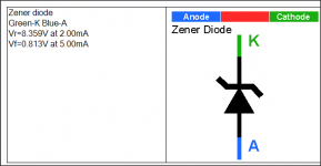
Salas, Woops, I found the LED package, which gives a forward voltage of 3.9v. I mistakenly must have used these instead of the proper leds.
this is the reference http://www.vishay.com/docs/83018/tlhb510.pdf
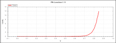
When I meaure voltage on one of the LEDs I get 3.24v using 9 v battery and 1 k resistor between positive. I should have paid attention to the voltage of the LEDs before I soldered them to the pcb but I thought they were the ones I ordered for the DCB1.
Are these wrong voltage LEDs the root of my problem...... giving me 14.4 volts vout instead of around 10v.
Will the dcb1 work as is, or should I change all the leds to around 1.9 volt LEDs. This will be a mess desoldering everything......
Thanks any ideas or further comments
this is the reference http://www.vishay.com/docs/83018/tlhb510.pdf
When I meaure voltage on one of the LEDs I get 3.24v using 9 v battery and 1 k resistor between positive. I should have paid attention to the voltage of the LEDs before I soldered them to the pcb but I thought they were the ones I ordered for the DCB1.
Are these wrong voltage LEDs the root of my problem...... giving me 14.4 volts vout instead of around 10v.
Will the dcb1 work as is, or should I change all the leds to around 1.9 volt LEDs. This will be a mess desoldering everything......
Thanks any ideas or further comments
Where you got that OMRON? Ebay?
I got 2pcs from local robotic component seller for free, he said he has so many of them. I even could not find anyone sell it on ebay. Why are you asking that? Is there any fake indication?

ok thanks Salas, now I know what to do, will revert when reordered and reinstalled 1.8 red leds. cheers, John
Get a nice desoldering gun also. No worries, mistakes happen.
I got 2pcs from local robotic component seller for free, he said he has so many of them. I even could not find anyone sell it on ebay. Why are you asking that? Is there any fake indication?
I don't know why it should be peculiar with the dropper resistors. Can you estimate how much current it draws after it clicks by measuring now Ohmic combination on the droppers and voltage across them? You could get NEC EA2 or NAIS TQ2 also. In the very start enough years ago a bunch of builders had used some OMRON, many NAIS 5V, then they almost exclusively used NAIS 12V and later NEC EA2 12V as the supplies changed on the markets. Does it cut off when you power off also? I.e. shorting output to ground?
P.S All types must be non-latch variation
Rdropper: 40.5R, Vdrop: 0.87V, I=21mA. I read in datasheet that G6H-2 5Vdc will have 28mA rated current. When i power off, I can hear relay click. When it's in off state, I measure output-ground resistance 0.2R, and when power on it's 250R. DC offset is 1-2mV for both channel
So it works OK. It will have 28mA with 5V nominal across it's coil. We will see when with 15VAC Tx if the 7812 is limiting at all on your mains now and it takes to lower Rdroper so much. 11.6V and not 12V from that chip is a bit suspicious. Very near to min spec 11.5V but possible also.
BC550 Vbe is 8.4V with additional 47R or 150R
Here is Philips original BC550C on BE mode, C no connection. Yours behaves alike. No problem there too.
Attachments
made some changes:
- change IRP240 & IRFP9240 with match pairs
- change 7812 with different brand
- relay Rdopper only use 47R
results:
- Vout: (+10.16V) & (-10.25V)
- Vdrop ccs: +rail (1.45V) & -rail (1.33V)
- Vgs: IRFP9240 ccs (4.31V), reg (4.21V) & IRFP240 ccs (4.36V), reg (4.28V)
- relay voltage: after 7812 (12.03V), after Rdopper 47R (10.9V), in4002 (4.2V)
- dc offset : R (2.1mV), L (0.8mV)
it's so fun to complete this, some kind of fun that can never be replaced by buying finished product + great support from this forum
the 4.2V across the 5V relay may be a bit too low.
Try adding a 100r parallel to the 47r. See how well the relay clicks ON. Measure the relay voltage when ON.
The output offsets should be negative, i.e. -0.8mVdc and -2.1Vdc
not positive.
A positive output voltage indicates that the follower is running at a current that is higher than Idss.
Try adding a 100r parallel to the 47r. See how well the relay clicks ON. Measure the relay voltage when ON.
The output offsets should be negative, i.e. -0.8mVdc and -2.1Vdc
not positive.
A positive output voltage indicates that the follower is running at a current that is higher than Idss.
After several additional parallel resistors from 100R to 10R, I get 2 possible choices of 47R parallel with:
- 20R (14R in total) resulting 4.93V on relay
- 10R (8.3R in total) resulting 5.15V on relay
Then I install 10R only (0.26V Vdrop, 26mA coming to relay) and get 5.02V measured on relay re-measure dc offset, negative probe on ground and measured L channel -1.2mV and R channel -1.7mV. previously i never noticed polarity on dc offset
- 20R (14R in total) resulting 4.93V on relay
- 10R (8.3R in total) resulting 5.15V on relay
Then I install 10R only (0.26V Vdrop, 26mA coming to relay) and get 5.02V measured on relay
re-measure dc offset, negative probe on ground and measured L channel -1.2mV and R channel -1.7mV. previously i never noticed polarity on dc offset
Last edited:
made some changes:
- change IRP240 & IRFP9240 with match pairs
- change 7812 with different brand
- relay Rdopper only use 47R
results:
- Vout: (+10.16V) & (-10.25V)
- Vdrop ccs: +rail (1.45V) & -rail (1.33V)
- Vgs: IRFP9240 ccs (4.31V), reg (4.21V) & IRFP240 ccs (4.36V), reg (4.28V)
- relay voltage: after 7812 (12.03V), after Rdopper 47R (10.9V), in4002 (4.2V)
- dc offset : R (2.1mV), L (0.8mV)
it's so fun to complete this, some kind of fun that can never be replaced by buying finished product + great support from this forum
Why do you need to match the P and N mosfets?
I also have positive offset on the out.
In the build guide this is written: "If you got DC audio out offset in the +/-5mV range, just drink a beer. Forget it."
So does it have to be negative or not?
What can be done to make it negative?
Such a small offset of +/-5mV is not a problem. Your next stage should be able to deal with it. Regardless if it positive or negative.
It it a lot less than seen from other designs
- Home
- Source & Line
- Analog Line Level
- Salas hotrodded blue DCB1 build