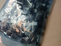
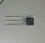
This is my last offer by the supplier before I get a refund. They sent me this photo, has anyone seen this batch number before? It's not a great photo, but it's worth a shot. They look legit. I see the 'BL' have some space between the the two letters. All of my legit 170s have the space. All of my fakes that I came across the two letters are touching, on every single one.
Thanks for your patience, and hopefully these posts help out other hobbyists.
Thanks for your patience, and hopefully these posts help out other hobbyists.
Attachments
Borbely did two articles on the jFET.
Part 1 fig 5.
But read the whole of the two articles.
Borbely is one of our best FET brains.
Awesome! Thanks a bunch. I'll read em this weekend
Hey everyone!
I have finished my DCB1 some months ago, and still I am very happy, but there is one thing I am a little bit worried about and I hope maybe someone has an Idea.
I am using the M-DAC Plus (Audiolab) as source which has a preamplifier built inside including a volume adjustment. Until now I always set the output to a fixed volume at the DAC and used the pot built in the DCB1 (Blue Alps). Now I think that it would be nice to remove the Alps and use just the volume adjustment of the DAC.
So, is it possible to just remove the Alps or should i use a fixed resistor at the input? And furthermore, do you think its good to do that, some experience anyone?
Also i wanted to know if anyone has built the dcb1 with Takman Carbon resistors? I read that they, compared to the metalfilm, smoothen a little bit the sound? I am thinking of changing them to Takman metalfilm (or PR9372???) and give it a try... Anyone has some experience?
Thanks and all the best,
Philip
There is a fixed resistor already. The 220k to ground. And it must always be there especially if the pot is removed else the circuit will give few volts DC at the output. But when you set a volume pot to max its out of the way with nearly zero Ohm in series. So you could put the Alps to max and control from the Audiolab only but still having a way to control volume in dcb1 for other music sources when needed.
If you need most transparent use Z Foil. Takman metal is very good too but not at that league. When the system as a whole has tendency to north of neutral i.e. bit glassy prefer carbon. There are some but Riken used to be best and it can still be found. Amtrans maybe its successor. Mind you such parts are bigger than what can be found in metal film.
If you need most transparent use Z Foil. Takman metal is very good too but not at that league. When the system as a whole has tendency to north of neutral i.e. bit glassy prefer carbon. There are some but Riken used to be best and it can still be found. Amtrans maybe its successor. Mind you such parts are bigger than what can be found in metal film.
Thanks for your fast reply! With "bigger" you mean the measurement?
hmm, i am still not sure... I am plannung/building the F5 at the moment using takman metal film. I think i will wait till its finished, maybe metal film in the f5 + carbon film in the dcb1 is a good combination anyway...
If I change the resistors to Amtrans in the dcb1 its enough to change the 8 resistors at the output ("Audio parts" in the bom)?
Thanks!!
I have finally completed my boards. Thankfully everything went ok on the first try. I would like to get my final measurements a little closer to one another, and would appreciate any input to do so. If I'm not mistaken, and please correct me if I'm wrong, closer matched Vref LED, closer matched R1, and closer match of b170?
I will be listening to the board in stock form for a little while, but eventually would like to go up to 400-600ma so the board will be coming apart and would like to do all of the final upgrades in one shot.
Board 1
R1-9240 side: 10.04 ohm 1.69V 163.0ma
R1-240 side: 9.74 ohm 1.51V 145.6ma
Vout: +9.61, -9.64
DC offset: R -1mv, L -.4mv
Board 2
R1 9240 side: 10.04 ohm 1.71V 164.73ma
R1 240 side: 10.14 ohm 1.52V 136.50ma
Vout: +9.80, -9.83
DC offset: R -1.12, L 0
Last edited:
Your measurements are really very good. You could use 10-12% smaller R on the negative sides than in the positives since the 240 Mosfets tend to show bit more VGS than the positives like 10% so they rob about that so more from the Leds combined Vf. Vrset=VFtotal-VGS remember. Or alternatively bit stronger Leds triplet in the 240's side. That is for your aesthetic pleasure and for bit better balanced dissipation between sides in higher hot-rod situations only though because such differences make no appreciable transconductance differences between polarities for such big MOSFETS.
I appreciate the quick reply.
In a dual mono configuration, would there be any issue with performance if there's a 20% difference in current in one channel, and ~14% in the other? I've never really measured a signal on an XLR to see how varied the voltage/current is per channel. Would it even make a difference in the performance of the signal, or the load on the other end? If it's not going to have any negative impact on performance, I won't even mess with it, aside from matching all 4 R1 closer when I upgrade the hotrod.
Thanks Salas
Try to keep the CCS currents within 10% in general. Take advantage of Led Vf manipulations is the easiest way when not having a bunch of near values resistors to play with as I explained above. Balanced XLR doubled up build has to do with well balanced impedances of the audio sections that are directly handling the signal phases than differences in the peripheral systems. But you would want those fairly alike too. For even radiation of heat at least. Well matched JFET quartets between channels (and not too different in idss between your two builds also I would like to believe). Also good tolerance signal passing resistors and then not much is left to really worry about.
do you happen to know what brand LEDs shipped with the kits? I'll buy a large quantity to guarantee the that I get the values I need. My quads of 170bl between boards are pretty close, ~10.1ma/10.2ma, Alweit hooked me up, but just incase, I have a bag of those too (the last bag was genuine). I followed an earlier post where you commented on the order of the fets by idss, I have it written in my project notes. I didn't measure the audio resistors, but I will make sure that they're on point. I may just get those fancy naked ones that all of the youngsters rave about.
Change of resistors 220K and 1M
Just as an update:
I have been running my balanced dcb1 with naked resistors tx2575 at the 220R position for a while but thought that the sound is sometimes a bit edgy. Not too much, but a bit with some recordings.
Now I have changed the 220K and 1M resistors from Teabag's kit (red?) to Caddock MK 132.
Holy cow, this sounds very different and so much better. I was not prepared for that! More body but still the detail as before. Absolutely love it!
I am really shocked and surprised about the difference in sound the right resistors at the right place can make!
Need to have a stiff drink now to calm down again ... and listen some more, of course. ;-)
There was a thread about trying resistors. Scorpion's favorite stuff. Has long time to log in. Hoping he is well. http://www.diyaudio.com/forums/analog-line-level/252030-salas-hotrodded-dcb1-resistor-tryouts.html
- Home
- Source & Line
- Analog Line Level
- Salas hotrodded blue DCB1 build