You can ask for a flux band on a custom EI. Its like an anti-magnetic belt around it reducing the leakage flux a lot. Make it a 100W order since EI gets hotter than toroid as it will be passing around 40W to the PSUs in your case.What is the recommended VA rating for a 15-0-15 transformer for 1A hotrod? I keep finding conflicting answers regarding size. Some say 50VA, 80VA and others 100VA. I think some of this variation has to due with not running the transformer near it's max rated load and heat.
Also, if it matters I am considering a custom wound EI core (with distance from the PCB of course).
I am using 80watts toroid it sings quite well)
Salas,
Thanks for the feedback. I will check it further with power amps to see whether I have the issue. Most likely it will go away on its own
Andrew, yes it appears around 1/4 of the total turn
Sent from my ONE A2003 using Tapatalk
Salas,
Thanks for the feedback. I will check it further with power amps to see whether I have the issue. Most likely it will go away on its own
Andrew, yes it appears around 1/4 of the total turn
Sent from my ONE A2003 using Tapatalk
A normal vol pot has a mechanical rotation of ~300° and an electrical rotation of ~270°the first 15-20 minutes
A quarter turn could be either 360/4 = 90°, or 270/4 = ~70°, but not 15 to 20'
Hi everyone
After using Mezmerize for two and a half - three years i decided to test my Hypnotize board.
Music does indeed sound better (a lot) but i do have one "issue". I fire the board up. I turn the volume knob at three o clock but the volume is a good bit lower than what expected. Ten to fifteen minutes later the volume does reach the normal expected volume.
Is that behaviour expected?
Luckily it was easy enough. A faulty irfp9140.
Replaced and everything works as should.
Are there fake irfps? I mean would anyone bother produce fake ones given the fact that they are quite cheap?
Low and mid improvement over the Mezmerize board sure is obvious at 200 ma. I wonder what kind of sorcery happens at 600ma.
Thanks for the help Salas.
And for the new toy of course.
Yes, it could be a messed up original but these mosfets never felt like the real deal to me. I remember when i bought them ( 2 maybe 3 years back ), they felt a tad light on the hand.. And the looks were, i dont know, compared to the ones i have on the Mezmerize (bought from mouser) these ones look like they spent a few nights out. Walks of shame may have happened too.
I think i ll replace all 4 of them, just to be sure.
I think i ll replace all 4 of them, just to be sure.
No, they are to diy
Oh ok, no worries.
Who can I purchase a DIY kit from?
Wondering the cost. Is there a link to a manual and breakdown of the specs? I was just recommended this board from a friend.
Usually the beginning of a thread has a mention about the board and how to purchase etc. not the case with this thread. Sorry I can't find this info.
Thanks for all the fish!
Just wanted to thank Salas and TeaBag, specially Teabag for sending me some more transistors F.O.C. Excellent service and highly recommended if a recommendation was ever needed.")
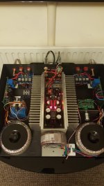
DC Offset is now -2mv on each channel, coupling this to my DC Coupled 3875's produce no problems so very happy camper here, over the coming weeks I will be testing to see if the buffer is required, the 3 pin sockets supplied make it very easy to bypass the DCB1 for comparison. I am just going to run my AV front channels through it for now which gets used for tv every day until i get time to do some serious listening, oh and to finish the build.
Salas, I did install a second set of 2.5ohm resistors, these get quite hot, i can hold them for about ten seconds before it hurts, I will have to measure the temp, I do have a quiet voice in my head saying, are they to hot to be so close to those psu caps? the heat sinks on the other hand are doing a grand job, the fets dont even feel very warm.
Just wanted to thank Salas and TeaBag, specially Teabag for sending me some more transistors F.O.C. Excellent service and highly recommended if a recommendation was ever needed.
DC Offset is now -2mv on each channel, coupling this to my DC Coupled 3875's produce no problems so very happy camper here, over the coming weeks I will be testing to see if the buffer is required, the 3 pin sockets supplied make it very easy to bypass the DCB1 for comparison. I am just going to run my AV front channels through it for now which gets used for tv every day until i get time to do some serious listening, oh and to finish the build.
Salas, I did install a second set of 2.5ohm resistors, these get quite hot, i can hold them for about ten seconds before it hurts, I will have to measure the temp, I do have a quiet voice in my head saying, are they to hot to be so close to those psu caps? the heat sinks on the other hand are doing a grand job, the fets dont even feel very warm.
Attachments
Last edited:
Is there a way to install the resistors on the all encompassing sink (insulated from it) and use extensions to the PCB?
Theres always a way, I could strip it down, drill and tap the angle bar then solder links, I dont even think the resistors need isolating but i would check, do you think the extra heat will shorten the life of the lytics because thats what i am thinking. Will having long ish cables in this position have any other detrimental effect? Maybe a lessor of 2 evils. Probably a good opportunity to fit 2 more feet because the case is sagging under the weight of the DCB1.
Last edited:
Measure the temperature on those nearby electrolytics first. There is a rule of thumb to derive their useful life from their ratings. Each 10C less than the max specified doubles their life expectancy. I.e. If there is a 1000 hours 85C spec it translates to 16000 hours at 45C. Resistors with ceramic back don't need isolation and simple continuity check from back to their leads will confirm.
- Home
- Source & Line
- Analog Line Level
- Salas hotrodded blue DCB1 build