P.S. Watch your power on/down system sequence as I see no relay in your build. What are those extra TO-220s for? Some post step down regulators for another circuit?
Yes, just a couple of 7812 and 7805 to feed an Arduino and the 12V trigger to startup the final amp (already developed) and a phono stage (designing).
The 5V will also be used for the input selector stage (relays based).
I just preferred to develop the audio section on another board: I have LDR attenuator, B1 buffer and mute relay there. Everything has to sit inside a 4cm height case, that's why you can see the 4 big caps lying down - now the PSU is less than 3cm including the 6mm spacers.
You got to allow higher CCS current so to feed those subsystems. Unless you are feeding those chip regs from the raw DC of the main reservoir capacitors.
No no, I'm getting my current directly from the reservoir cap. I don't want to touch your baby
")
At the very beginning I designed a separate power supply, but I don't think that few hundreds of mA will create any real problem.
Anyway, later on I will increase the current at least to see if there is a real difference in sounds (I'm curious).
But with all those extra loads and/or hot rodding, the bridge diodes should be monitored for heat still.
Good point, I'll monitor them.
Ok, testing everything I have found something unexpected. If I don't apply any signal to the B1 buffer, the output DC voltage on one channel is 0V and on the other channel is 150mV. Sorry if you already covered this scenario in one of the previous page of this thread. Is it possible and acceptable? Something wrong in my implementation (bad solder joint, not well matched K170)?
Ok, we'd like to have 0V, but in real life what's an acceptable DC offset?
Ok, we'd like to have 0V, but in real life what's an acceptable DC offset?
Guys, thank you for the precious advice.
Yes, the problem was the matching: I bought 2 couple of already matched K170 from ebay just to avoid to do extra work.
I didn't have so many spare k170 (just four) but I tested few combination of them and now I have something that works better: 2.8mV
Next time I will ask to someone in this forum to have a well matched set of 4 K170
Just a generic question regarding K170. Testing the ones I have here I have found better values in case of K170 with the same tag "K170 BL xx" in my case the "xx" was '3A'. Is there any meaning in this last two characters? I haven't found anything using google
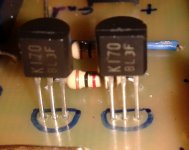
Two pictures (the best my mobile can do), not sure you can see what you are looking for.
In the first one you can see 2 of the 4 'ebay' K170, the ones perfectly matched (DC=0.2-0.1mV)
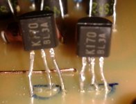
In the second picture you can see the 'not so well matched' k170s. The one on the left comes from ebay and the one on the right comes from a standard channel (mouser if I well remember) - they look like the same to me. As you can see, life was harder for these components: lots of test directly on the circuit.
In the first one you can see 2 of the 4 'ebay' K170, the ones perfectly matched (DC=0.2-0.1mV)
In the second picture you can see the 'not so well matched' k170s. The one on the left comes from ebay and the one on the right comes from a standard channel (mouser if I well remember) - they look like the same to me. As you can see, life was harder for these components: lots of test directly on the circuit.
Attachments
They all look alright for proportions, pins style, and print. I see you populated them in reverse to your outline marks.
Yes, but they are right this way
I picked up a generic transistor during the design of the pcb but before soldering I review the datasheet of K170 and ... I reversed the orientation.
Hi again!
Got 4 new jfets from tea-bag which fixed the dc offset.
I replaced the i/v stage for my buffalo 3 dac (whose distortion in voltage out mode is anyhow lower than that of my power amplifier, so i figured I should try it) with a dual dcb1-setup.
It sounds really good! I didn't think my speakers (dtqwt mk2) could play with so much pondus=)
Thanks for all the help and this excellent and fun project!
Best regards!
Enjoying others work
Hi.
I bought this nearly finished and have completed it. Lots of goddies on board. The leds light up and V+/- is about 10V but I only tested it swiftly as my trafo is 18V so no closer readings yet.
Would it be ok to change the MUR860's to BYW29E-200? This because I want to mount the diodes on the baseplate for cooling and the legs on the MURs are to short. Of course I could prolong them if that is better.
Some pics
Regards
Hi.
I bought this nearly finished and have completed it. Lots of goddies on board. The leds light up and V+/- is about 10V but I only tested it swiftly as my trafo is 18V so no closer readings yet.
Would it be ok to change the MUR860's to BYW29E-200? This because I want to mount the diodes on the baseplate for cooling and the legs on the MURs are to short. Of course I could prolong them if that is better
.Some pics
An externally hosted image should be here but it was not working when we last tested it.
An externally hosted image should be here but it was not working when we last tested it.
Regards
You can insert the diodes from the bottom and that allows bottom face cooling.
The diodes would be mouted with their cooling face down and their printed face up.
The lead outs are bent up at 90° and pass through the PCB holes.
If the leadouts need to be soldered on the bottom of the PCB (not plated through holes), you would need to solder these leads before bolting.
The diodes would be mouted with their cooling face down and their printed face up.
The lead outs are bent up at 90° and pass through the PCB holes.
If the leadouts need to be soldered on the bottom of the PCB (not plated through holes), you would need to solder these leads before bolting.
You can insert the diodes from the bottom and that allows bottom face cooling.
The diodes would be mouted with their cooling face down and their printed face up.
The lead outs are bent up at 90° and pass through the PCB holes.
If the leadouts need to be soldered on the bottom of the PCB (not plated through holes), you would need to solder these leads before bolting.
Thank you AndrewT. Are the BYW29E-200 up for the job? The MURs can take 600V and the BYWs 200V each.
Regards
The Peak Inverse Voltage (PIV) is roughly three times the transformer AC voltage.
If you use 18+18Vac then the required PIV is 108V (+ ~15% for variations in supply). This would need 200V diodes.
But in a bridge rectifier each diode only gets exposed to half the PIV so 100V diodes are required for a discrete Bridge. An integrated bridge rectifier needs a 200PIV.
You certainly don't need 600V diodes.
A normal DCB1 with 15Vac+15Vac would work with 50V diodes.
Last edited:
Thanks again. Usefull tutoring as usual
Regards
Regards
The Peak Inverse Voltage (PIV) is roughly three times the transformer AC voltage.
If you use 18+18Vac then the required PIV is 108V (+ ~15% for variations in supply). This would need 200V diodes.
But in a bridge rectifier each diode only gets exposed to half the PIV so 100V diodes are required for a discrete Bridge. An integrated bridge rectifier needs a 200PIV.
You certainly don't need 600V diodes.
A normal DCB1 with 15Vac+15Vac would work with 50V diodes.
- Home
- Source & Line
- Analog Line Level
- Salas hotrodded blue DCB1 build