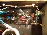
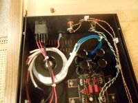
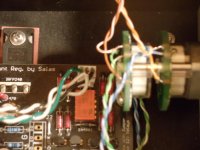
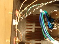
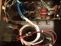
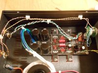
I can't see anything obvious from your pictures. In mine there is a delay of approx 12 seconds after switching on before the relay clicks. Your voltages seem a little on the low side, i'd need to check but if i remember correctly mine were just over 10V. That could be the reason but others here are better placed to judge that. What voltage does your transformer produce?
The regulator output voltages are very dependent on Idss of the jFET and the Vf of the LEDs.
The Buffer does not care what the voltage tolerance is. 10V+-3V will work.
The relay diode voltage tells you, that DCB1 does not have voltage telling the relay to turn ON.
Check the 7812 for voltage on it's input and output. Don't short it ! use other traces where a slipped probe will not cause a short.
If the regulator is OK, then we need to investigate the transistors that turn ON the relay.
7812 input voltage = 10.00v
output voltage = 8.75v
That's too low. Should be as high as across any main filter capacitor at a level of AC secondary times 1.20 to 1.35. Check if all diodes are alright or the 7812 itself is faulty. Check AC input level on the Tx connector. Wiring there should be reading 2xsecondaries ACV nominal across the edges.
Hi all,
I built a DCB1 Hotrodded board (TeaBag components) and at first power on everything seemed to be ok and I was an happy guy.
Then the fall!... While trying to case the board something happened (I suppose bad soldering...) and the 5 LEDs string on IRPF240 side started having a total Vdrop voltage of more than 15V!!! circa 3V Vdrop on each LED (measured each one vdrop with DMM)... and consequently -Vout = -22.0V!!! (initially it was -9.90V).
After this I completely removed all 5 LED and re-soldered one by one after testing each one (had to substitute one with a new because damaged)
It was working well again but.... this morning everything happened again the same way!!!
What I have to check and which one could be the possible reason for this behavior?
Notice 1: in each LED string there are red leds and one green (3 LED strings are 2 red + 1 green, 5 LED strings are 4 red + 1 green). I have seen DCB1 built this way
Notice 2: all the leds light up regularly (no polarity inversion)
Notice 3: the other side is still ok with +Vout = +10.0V.
Thanks,
Saverio
I built a DCB1 Hotrodded board (TeaBag components) and at first power on everything seemed to be ok and I was an happy guy.
Then the fall!...
After this I completely removed all 5 LED and re-soldered one by one after testing each one (had to substitute one with a new because damaged)
It was working well again but.... this morning everything happened again the same way!!!
What I have to check and which one could be the possible reason for this behavior?
Notice 1: in each LED string there are red leds and one green (3 LED strings are 2 red + 1 green, 5 LED strings are 4 red + 1 green). I have seen DCB1 built this way
Notice 2: all the leds light up regularly (no polarity inversion)
Notice 3: the other side is still ok with +Vout = +10.0V.
Thanks,
Saverio
Hi Salas,
I tried to make my best to understand your request.
JFET (2SK170 near leds) has Vgs=15.3V (exactly as the symmetric jfet on irfp 9240 side)
MOSFET (the irfp 240 nearest trafo) has Vgs=4.9V Vgd=0 Vds=4.9 (quiet different from irfp 9240 on the other "good" rail that has Vgs=3.9 V Vgd=10.2 Vds=-6.3)
Maybe that 240 MOSFET is the problem?
ANYWAY THANKS. .. For the little time I could ear music with this board it was amazing . Hope I'll be able to fix...
I tried to make my best to understand your request.
JFET (2SK170 near leds) has Vgs=15.3V (exactly as the symmetric jfet on irfp 9240 side)
MOSFET (the irfp 240 nearest trafo) has Vgs=4.9V Vgd=0 Vds=4.9 (quiet different from irfp 9240 on the other "good" rail that has Vgs=3.9 V Vgd=10.2 Vds=-6.3)
Maybe that 240 MOSFET is the problem?
ANYWAY THANKS. .. For the little time I could ear music with this board it was amazing
Jfet Matching and Range
Working on my Mezmerize and have come up to several questions.
Which jfet to place where?
I have 4 closely matched sk170 at 8.2 ma that come from Spencer. But would prefer to keep them as they are a matched quad at the same Idss with j74.
I have 8 linear systems lsk 170 with range of in the following Idss 7.4, 8.07, 8.17, 8.77, 10.74, 10.86, 11.43, and 11.83 mA. The DiyAudio store has only D grade lsk170's left. Idss (18-30).
I also have 12 k117 that came with the sslv regulator kit (from Tea-Bag), but I haven't measured or matched.
Questions are
1. Are the k117 useful for the mezmerize? As the unmatched portion? or the Matched portion? and if so how close to match.
2. Anyone know of a source of 4 matched lsk 170's?
3. If I use the matched quad from spencer w Idss of 8.2 mA which lsk 170's should I use?
Plannning on hot rodding to 200mA.
Thanks,
1. Only in the regs area, very nice there, no matching. Just roughly mirror them by idss proximity samples between symmetrical pcb positions after you survey your stash.
2. Nope, ask Tea as he shops around
3. Use the K117s for the rest or do as in (1) for your LSKs. I would save the LSKs for future projects use in signal areas where their higher transconductance matters more. The dcb1 quad should be very well matched K170BL or analogous Idss LSK170 though. No other.
I am currently building a balanced pre-amp with two boards and kits provided by Tea Bag.
Both boards power up nicely (yes!), the voltage out readings for one board is +9.81 and -9.31 and for the other +9.31 and -9.32.
Is it a problem that the v+ values for the two boards are quite different for a balanced setup or should they be closer matched? If this is so, what to do?
Both boards power up nicely (yes!), the voltage out readings for one board is +9.81 and -9.31 and for the other +9.31 and -9.32.
Is it a problem that the v+ values for the two boards are quite different for a balanced setup or should they be closer matched? If this is so, what to do?
The precision of the dual polarity supplies does not matter. The Follower does not care what voltages are on the supplies. Roughly equal for the dual polarity and "clean", no ripples, no interference.
For a balanced impedance set up, what does matter is precision of the output and input impedances.
Aim for better than 0.1% for resistances and better than 1% for capacitances.
If you can get 10 times better than those targets, go for it.
This applies to the Source as well as the Receiver.
For a balanced impedance set up, what does matter is precision of the output and input impedances.
Aim for better than 0.1% for resistances and better than 1% for capacitances.
If you can get 10 times better than those targets, go for it.
This applies to the Source as well as the Receiver.
Last edited:
- Home
- Source & Line
- Analog Line Level
- Salas hotrodded blue DCB1 build
