mbain, I just would like to share my experience for EMI IECs. I tried coupe of TE and Schaffner made EMIs which used Cy caps (L<->GNG and N<->GND) and my sound degrade dramatically. Some guys here advised to use EMI with no Cy caps and suppression should start at 10kHz and up. Not lower suppression.
Davym, thanks for your reply. Now I understand the diagram with respect to the placement of jumpers necessary for ones specific mains voltage. In my case I am working with USA home voltages 110-115v. As a newcomer to this hobby I need to ask how does one either purchase or fabricate the required jumpers? I suspect the jumpers are integrated into the fuse module that allows one to choose either 115v or 230v by inserting the module with one side or the other upward according to the printed voltage printed on the end of the module. Yes?
I can't see from the diagrams how you fit the jumpers, if you post a few photos of the unit it might help. Also alexkosha makes a good point about using filtered IEC sockets in the first place, technically they make good sense and i did consider using them but i have read several reports on here about them degrading sound quality. You might be able to bypass the filter to see if you need it in the first place and to see if it does actually harm sound quality when used. I use unfiltered fused IEC sockets in my builds and have had no real issues. I did get interference from a faulty SMPS unit which was plugged into the same supply as my system a while back. I changed the SMPS which sorted the problem.
I use CAT5e a lot, but I use twisted pair insulated 0.6mm diameter hook up wire more.Andrew,
Have you tried solid core CAT6 or 7 (just skin the cable and grad one pair). They work really good. Specs should also be very good since they're designed for high speed over long distances.
Do
The CAT5e is hard drawn and more susceptible to fatigue cracking if subject to vibration. The hook up wire is softer, it might be annealed after drawing.
I have ~1 km of CAT5e around the house and that avoids the need to twist longer pairs.
3m pairs is a convenient maximum length for me to hand twist ( I don't use the hand drill method, it twists the individual cores).
But, I am moving to star quad in upto 3m. I did another 2.5m pair using CAT5e last week using my door knob method.
The star quad is a bit more robust and I thought it worth taking the risk to use CAT5e for an interconnect.
mbain, I just would like to share my experience for EMI IECs. I tried coupe of TE and Schaffner made EMIs which used Cy caps (L<->GNG and N<->GND) and my sound degrade dramatically. Some guys here advised to use EMI with no Cy caps and suppression should start at 10kHz and up. Not lower suppression.
If you hear degradation of the audio after fitting a correctly rated Mains supply input filter, then I will argue that your audio system is faulty !...............Also alexkosha makes a good point about using filtered IEC sockets in the first place, technically they make good sense and i did consider using them but i have read several reports on here about them degrading sound quality. You might be able to bypass the filter to see if you need it in the first place and to see if it does actually harm sound quality when used. I use unfiltered fused IEC sockets in my builds and have had no real issues. I did get interference from a faulty SMPS unit which was plugged into the same supply as my system a while back. I changed the SMPS which sorted the problem.
Find and sort the fault !
So, i've decided to build a Hypnotize Black DCB1, encased in wood.
While i will try to refrain from hot-rodding it very much, at 200mA CCS current i'm still looking at some heat sinking to keep temps down inside the box to try to extend the life of components inside.
Imagine a plain wooden box, where part of the bottom plate is cut out and replaced with something like this:
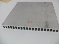
This heat sink measures 140 by 140mm, and is 12.7mm tall. The plan is to mount the MOSFETs to this heat sink, secure the heat sink to the chassis so it doesn't hang from and therefore risk stressing the solder joints, and have the heat sink protrude a couple of mm beneath the bottom of the box, but still have some airflow around the heat sink provided by the feet.
If anybody has their Hypnotize DCB1 Black PCB(if there is a difference between the boards) sitting in front of them, and can be bothered, could you please measure the distances in X and Y between the points formed by the four screws fixing their MOSFETs to the chassis below? I only need a ballpark figure to see if i can even find a single heat sink that can do the trick(preferred), or if i need to get two heat sinks instead.
And i would very much value your input on this arrangement, I realize quite a bit of heat is going to be radiated upwards and into the chassis, and some of the heat that is radiated down will get reflected right back to the heat sink by the surface which the box sits on, about 5-7mm away. It's just that i'd like to keep vents in the chassis to a minimum, to minimize dust ingress and for aesthetics.
While i will try to refrain from hot-rodding it very much, at 200mA CCS current i'm still looking at some heat sinking to keep temps down inside the box to try to extend the life of components inside.
Imagine a plain wooden box, where part of the bottom plate is cut out and replaced with something like this:
This heat sink measures 140 by 140mm, and is 12.7mm tall. The plan is to mount the MOSFETs to this heat sink, secure the heat sink to the chassis so it doesn't hang from and therefore risk stressing the solder joints, and have the heat sink protrude a couple of mm beneath the bottom of the box, but still have some airflow around the heat sink provided by the feet.
If anybody has their Hypnotize DCB1 Black PCB(if there is a difference between the boards) sitting in front of them, and can be bothered, could you please measure the distances in X and Y between the points formed by the four screws fixing their MOSFETs to the chassis below? I only need a ballpark figure to see if i can even find a single heat sink that can do the trick(preferred), or if i need to get two heat sinks instead.
And i would very much value your input on this arrangement, I realize quite a bit of heat is going to be radiated upwards and into the chassis, and some of the heat that is radiated down will get reflected right back to the heat sink by the surface which the box sits on, about 5-7mm away. It's just that i'd like to keep vents in the chassis to a minimum, to minimize dust ingress and for aesthetics.
Attachments
If you hear degradation of the audio after fitting a correctly rated Mains supply input filter, then I will argue that your audio system is faulty !
Find and sort the fault !
I realy doubt that I have some fault or even minor issue with my gear. I tested these on my builds and also on comersialy made units that I have in my possesion (Triode Corp from Japan tube preamp and poewer monoblocks and NAD M5 CD player and so on) . Again and fo my case, no EMI unit alwaise sounded better for me. Maybe it is just for me....! I'm not trying to convince the forum. Just expessing my tests results.

If you stand the case "up" so that air can pass up through the fin gaps then the sink will cool the mosFETs.So, i've decided to build a Hypnotize Black DCB1, encased in wood.
While i will try to refrain from hot-rodding it very much, at 200mA CCS current i'm still looking at some heat sinking to keep temps down inside the box to try to extend the life of components inside.
Imagine a plain wooden box, where part of the bottom plate is cut out and replaced with something like this:
This heat sink measures 140 by 140mm, and is 12.7mm tall. The plan is to mount the MOSFETs to this heat sink, secure the heat sink to the chassis so it doesn't hang from and therefore risk stressing the solder joints, and have the heat sink protrude a couple of mm beneath the bottom of the box, but still have some airflow around the heat sink provided by the feet.
If anybody has their Hypnotize DCB1 Black PCB(if there is a difference between the boards) sitting in front of them, and can be bothered, could you please measure the distances in X and Y between the points formed by the four screws fixing their MOSFETs to the chassis below? I only need a ballpark figure to see if i can even find a single heat sink that can do the trick(preferred), or if i need to get two heat sinks instead.
And i would very much value your input on this arrangement, I realize quite a bit of heat is going to be radiated upwards and into the chassis, and some of the heat that is radiated down will get reflected right back to the heat sink by the surface which the box sits on, about 5-7mm away. It's just that i'd like to keep vents in the chassis to a minimum, to minimize dust ingress and for aesthetics.
So, i've decided to build a Hypnotize Black DCB1, encased in wood.
While i will try to refrain from hot-rodding it very much, at 200mA CCS current i'm still looking at some heat sinking to keep temps down inside the box to try to extend the life of components inside.
Imagine a plain wooden box, where part of the bottom plate is cut out and replaced with something like this:
This heat sink measures 140 by 140mm, and is 12.7mm tall. The plan is to mount the MOSFETs to this heat sink, secure the heat sink to the chassis so it doesn't hang from and therefore risk stressing the solder joints, and have the heat sink protrude a couple of mm beneath the bottom of the box, but still have some airflow around the heat sink provided by the feet.
If anybody has their Hypnotize DCB1 Black PCB(if there is a difference between the boards) sitting in front of them, and can be bothered, could you please measure the distances in X and Y between the points formed by the four screws fixing their MOSFETs to the chassis below? I only need a ballpark figure to see if i can even find a single heat sink that can do the trick(preferred), or if i need to get two heat sinks instead.
And i would very much value your input on this arrangement, I realize quite a bit of heat is going to be radiated upwards and into the chassis, and some of the heat that is radiated down will get reflected right back to the heat sink by the surface which the box sits on, about 5-7mm away. It's just that i'd like to keep vents in the chassis to a minimum, to minimize dust ingress and for aesthetics.
The idea is good but you prob. need some more length to be able to pickup the mounting holes in the pcb.
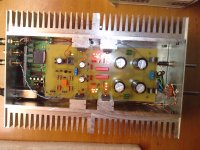
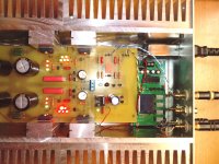
I made some rough measurements , imagine looking from above with the AC input in the lower end of the drawing.
I used similar approach but made my sink out of 1mm copper.
The area is 180mm x 220mm and has no problem with 10ohmsCCR resistors (about 170ma shunt) i even tried a 5ohm in parallel with the 10ohm increasing the current to at-least the double and the copper worked swell.
An externally hosted image should be here but it was not working when we last tested it.
An externally hosted image should be here but it was not working when we last tested it.
Last edited:
I used similar approach but made my sink out of 1mm copper.
Hey that is exactly the information i was looking for, thanks a lot.
Looking good!
Hey that is exactly the information i was looking for, thanks a lot.
Looking good!
Go for wood,
Scandinavian tradition...
")
An externally hosted image should be here but it was not working when we last tested it.
An externally hosted image should be here but it was not working when we last tested it.
DSC00845 - My Photo Gallery
In order to wire my dual primary transformer in the parallel configuration for a 110v application as shown on the referenced image, where do I attach the two red primary wires, to A & B ? The black primary wires would then attach to terminals C & D. Yes or No?
In order to wire my dual primary transformer in the parallel configuration for a 110v application as shown on the referenced image, where do I attach the two red primary wires, to A & B ? The black primary wires would then attach to terminals C & D. Yes or No?
DSC00845 - My Photo Gallery
In order to wire my dual primary transformer in the parallel configuration for a 110v application as shown on the referenced image, where do I attach the two red primary wires, to A & B ? The black primary wires would then attach to terminals C & D. Yes or No?
That's what it looks like to me so yes.
Remember to use a light bulb tester in the 110v supply when you power it up.
Interesting phenomenon today. Succeeded I correctly wiring my Antek transformer to AC mains and to DCB1 pcb. All LED's still lighting as before. Placed DCB1 in audio chain between CD player and Amp Camp mono amps, and got no sound out of speakers. Amps functioning as speakers are loud with CD connected directly to amps. Review of input/ output, attenuators wiring appears good. Ideas?
The DCB1 is in mute mode until the relay clicks. In this thread there are posts which show various points to take measurements from. Rail voltage etc. Maybe you could post some pictures of the build along with some measurements. The more info you give people the better. My guess is it's probably something power supply related....
- Home
- Source & Line
- Analog Line Level
- Salas hotrodded blue DCB1 build