Thank you!
I've got two 4"x10"x1" heatsinks from heatsink usa that are 0.9 deg C/W/3". For a 4" piece, that means 3/4 x 0.9 = 0.675 deg C/Watt for my sink.
If my calculations are correct a stage 2 hotrod means 600 ma over 10volts per mosfet = 12 watts per rail. That's using the 3R3 resistor.
That means each sink ought to rise only 8.3 degrees C.
Going 1.5 amps/mosfet gives 1.5 x 10 x 2 = 30 watts, for a rise of 0.675x30 = 20.8 degrees C.
So, there is enough heatsink here, but what of the MUR860?
It looks like they will need sinking at the 1.5 amp level, but I don't know how much.
Will they also need it at the 600 ma level?
thanks!
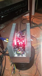
There is a current to forward drop curve on diodes datasheets, from there you can estimate power dissipation on them at each setting. Although those MUR got a high melting point, I would assist them beyond 600mA since its constant current not giving them a chance to breath.
It looks like the data sheets suggest that when running them without a heatsink you can expect to see 60 deg C/W temp rise. I have not looked to closely otherwise, but when pushing 2 amps, you can expect around 2 watts dissipation, so a rise of 120 deg C above ambient is expected
The chart of case temp vs forward current suggests that this is well within operating limits.
The chart of case temp vs forward current suggests that this is well within operating limits.
You could have 40C+ ambient in that box. RΘJA is 73C/W on the general thermal quotes though. But they look like dissipating about 1.2W each on high internal temps at 2A. It would be better running silicon under 100C or less for longevity, that is why we put those diodes on the pcb's edge so you can sink them on chassis floor or use mini sinks. You test in your own box thermals and decide. They should either be independently sinked touching nothing else or insulated to a common sink/chassis if you will. Fuse the thing on what rating your transformer has printed on its label anyway.
Attachments
The new relay makes an audible click!!!
Tonight, I hope to finish the task. Just deciding on a power switch now.... or maybe none... either a metal toggle, or a lighted rocker. I am leaning towards the rocker, because it is pretty, but I think I will tire of it... the metal toggle works since the casework and heatsinks are all natural aluminum. Or maybe no switch....
Does anyone leave their hotrod on at all times? 600 ma or more?
Very roughly the C/W rating varies with the square root of the height...........I've got two 4"x10"x1" heatsinks from heatsink usa that are 0.9 deg C/W/3". For a 4" piece, that means 3/4 x 0.9 = 0.675 deg C/Watt for my sink.........
If 3" is 0.9C/W @ deltaT=75C
the 4" is sqrt(3/4)*0.9 = 0.78 @ deltaT=75C.
If deltaT ~8C the apply a de-rating factor (DF) of ~ 1.6.
i.e. deltaT (s-a) ~ 1.6 * 0.78 * 0.9 * 12W ~ 13C
For 30W expect the DF to be somewhere from 1.3 to 1.5.
Thanks AndrewT!
I thought it was linear... this makes a HUGE difference, as the C/W for a 12" piece is not 4x the rated value but only 2x. Hmmmm.... my F5T needs WAY more heatsink. Back to the drawing board on that one...
BTW: Where do the DF = 1.x factors come from? Is there a table somewhere?
I thought it was linear... this makes a HUGE difference, as the C/W for a 12" piece is not 4x the rated value but only 2x. Hmmmm.... my F5T needs WAY more heatsink. Back to the drawing board on that one...
BTW: Where do the DF = 1.x factors come from? Is there a table somewhere?
BTW if your DeltaT is equal to their DeltaT then the DF=1.
BUT!!
the testing and specification value they give is with the whole backplate at isothermal condition.
i.e. the dissipating device contacts the whole backplate during the test, not a little bit where each device is mounted.
BUT!!
the testing and specification value they give is with the whole backplate at isothermal condition.
i.e. the dissipating device contacts the whole backplate during the test, not a little bit where each device is mounted.
 Whoops! The thermal resistance (degC/Watt) not DF ( that is the derating factor ).
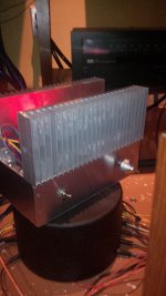
- Home
- Source & Line
- Analog Line Level
- Salas hotrodded blue DCB1 build