I apologize for asking this as I think this has been discussed in prior posts... Having problems fiding things on this thread with so many pages.
I think some are running jumpers on two resistor spots I've got the arrows on. Or 1 resistors. What is the driver on the resistors VS Jumpers in these two spots?:
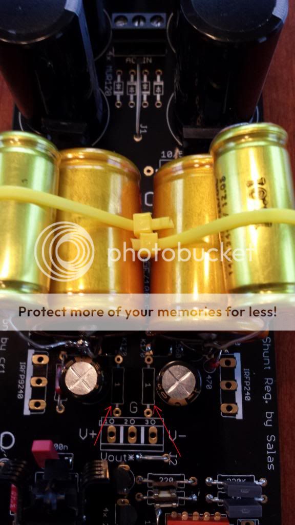
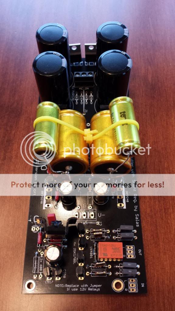
I think these are the two resistors I got from Tea Bag for these two spots YES/No:

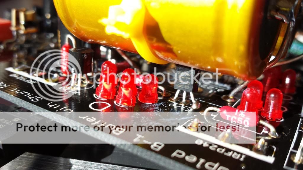
Photo of where I'm at:
I think some are running jumpers on two resistor spots I've got the arrows on. Or 1 resistors. What is the driver on the resistors VS Jumpers in these two spots?:
I think these are the two resistors I got from Tea Bag for these two spots YES/No:
Photo of where I'm at:
The 1 Ohm resistors have been designed in there for practical purposes only. I.e. for when using the board as a general shunt reg. Someone can find the running current in the voltage sources easily when dividing the voltage drop on them by their value. Then he may exploit that for some custom Vout trim with resistive elements. You may use jumpers when it is for a typical DCB1 with pure LEDS reference. Makes no difference. Resistors look nice and are a check point in that case, nothing more.
Shouldn't the safety earth(from IEC) be bolted directly to chassis using thick solid core wire, shortest possible length? CL-60's should only be used when connecting to this earth bolt from a STAR/Main Audio Ground point(s).I connected from the centre power in connector to chassis through an CL60.
I have been looking at a few different configurations. One that struck my eye is:
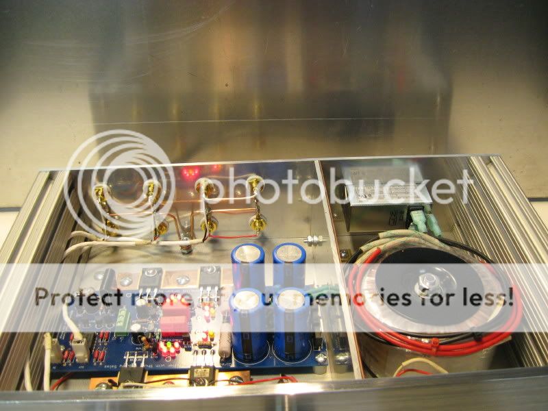
I hope the builder/owner of this amazing DCB1 doesn't mind me using it as an example..
I have thick copper buss wire like is used above. Can I common Input and Output RCA grounds with it?? Then bolt directly to chassis as seen above?
Or would it be better to connect input ground to center pin of its respective molex? Then ground the board itself using the center 'G' in the Vout location?
It would create the same connection, i know. Just wondering if it would be optimal to just go direct to board using the thick buss wire?
I have a Khozmo 10K attenuator that will be installed very soon, I am just waiting on a shaft extender kit in the mail. Going to set up without it because I can't wait any longer to give this baby a listen.
Any thoughts would be much appreciated. Thanks guys
madisonroberts,
I'm a few steps behind. I have the same attenuator.
My thought was that for one channel you'd wire RCA INPUT Ground to one of the Attenuator GND as well as the PCB DBC1 Input ground. Then the RCA (+) would wire to the IN 1 of the attenuator and the out 1 (+) to the (+) PCB DBC1
I'm a few steps behind. I have the same attenuator.
My thought was that for one channel you'd wire RCA INPUT Ground to one of the Attenuator GND as well as the PCB DBC1 Input ground. Then the RCA (+) would wire to the IN 1 of the attenuator and the out 1 (+) to the (+) PCB DBC1
for one channel you'd wire RCA INPUT Ground to one of the Attenuator GND as well as the PCB DBC1 Input ground
Actually, I think I was just going to run the Input Signal (left and right) to attenuator but run only one ground wire. I have tied a buss wire around RCA jacks to create a common ground. Then the ground wire to PCB input (center pin on molex).
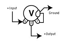
+RCA IN to pot IN. RING RCA IN TO POT GND. Repeat for channel 2. No link between rings.
POT WIPER pins channel OUTputs to DCB1 INputs. POT GND pins locally linked. One wire from them to DCB1 middle pin IN (GND).
DCB1 OUT1, GND, OUT2 to RCA OUT1+, 0(linked rings), RCA OUT2+
RCAs insulated.
IEC EARTH PIN to chassis (short link). DCB1 to chassis can ground from ground linked POT's body. Or a sturdy link from Vout middle tap to chassis, and the pot will find ground when attached to chassis without GND PINs to body link.
Attachments
Both sets of my 5 LED groups do not light up. Both sets of my 3 LED groups do fully light up.
I've got the Long pin/round side ANODE of the LED in the square hole on all 5 in the two 5 LED groups
I've got the Long pin/round side ANODE of the LED in the ROUND hole on all 3 of the two working 3 LED groups.
I was thinking I was correct with my LED install from reading this:
Square hole is Led's anode in this pcb as crt designated that half circle symbol over the 5 Led groups, when its the cathode in the 3 Led groups.
ANY ideas on why my two 5 LED groups do not light up or what to check next?

https://en.wikipedia.org/wiki/File:LED,_5mm,_green_(en).svg
maybe this helps, can't see pic well except for last one - which looks right.
maybe this helps, can't see pic well except for last one - which looks right.
No, it does not follow this.
Is it possible that a typo on the board is in play for the 3 LED spot?
Take a look at my first pic... It has the 3 spot that for me is working. An LED orientation image is on the board. This Image has the Anode going into the round. You don't need to see my LED next to the image. You can see the square sticking out from under the FLAT side of the LED
I think working with +/- parts of the reg, the led sitation is reversed on one side, So not I guess A good rule of thumb.
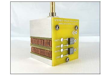
This is a large pic that may help. I believe the LED symbol of CRT is correct, that flat side is cathode is all cases, and to wire that way, ignoring pad shape. I will still need to confirm myself, via inspecting my own units to see if this is all true.
Dcb1production - My Photo Gallery
Also Can see the bulb here on the 3 led portions. The LEDs all sail in same direction in pic.
http://www.diyaudio.com/forums/gallery/showfull.php?photo=5330
Can see the bulb here on the 3 led portions. The LEDs all sail in same direction in pic.
Last edited:

- Home
- Source & Line
- Analog Line Level
- Salas hotrodded blue DCB1 build