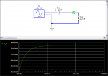
Niko do you mind explaining what does the 1M resistor do? Is it necessary?
Also, what would the above diagrams look for 220K input imp? I have also used 2,2uF ones
It references the cap for not holding charge to avoid thump noises.
Attachments
Salas,
I have settled on ~90ms as the RC for the DC blocking filter in my systems.
I have presented this many times and I get repeatedly told that I cannot possibly hear any difference in bass response with the filter set this low.
You are proposing 4u5F and 47k for an RC of >210ms which is more than an octave lower.
What do you find when using this frequency for your power amp roll off ?
Bigger sound stage.
Thanks again Salas, 4.7uf it is (wallet says ouch!).
4 7uF 250V PIO Capacitors Hi End K75 10 Lot of 4 New | eBay
These are great & cheap. The listing has the wrong picture - FYI
Can your amplifiers pass these VLF without adding their own phase and level distortions?
My philosophyy is that the input filters must be used to define the passband.
Once I have done that, the internal roll-offs must allow that chosen passband to operate with as little interference as possible and the PSU must also allow that passband to operate.
If I change the input filters down by an octave, or more, I would have to change the amplifier and the PSU as well. Well I did and came up with my preferred input filter determined passband (that suited me and my system). But I would not then change the input filter alone. That corrupts the amplifier's ability to operate over the now wider passband.
Do you see the problem?
Suggesting to another that they adopt a >210ms filter may be anathema to the operation of his system.
I think the Member should progressively increase the passband of the DC blocking capacitor from a high value of around 10ms to determine when the amplifier+ filter no longer give improvements, as limited by the complex amplifier + PSU interactions.
Only then go out and buy expensive capacitors to match up with the values found.
Simply jumping to 2u2F//2u2F//0u1F is not a good way to arrive at a value for the DC blocking capacitor. It is possible that 0u68F works, or just as likely 1u8F, or any value. But the chances of 4u5F being correct for his amp are pretty low in my estimation.
Last edited:
I have experience with the SCR tin foil if its comparable, and I find it dark and heavy. I also used supreme, supreme silver in oil and supreme silver gold oil.
I think you are right about this but it fits in my and friends stereo. That is why I like them. But we use Silver Cables with Silk isolation.
I think you are right about this but it fits in my and friends stereo. That is why I like them. But we use Silver Cables with Silk isolation.
Subjective synergy is a whole bunch of expert decisions. I can appreciate how you mixed those.
Guys what is the general rule about time shifting in this case? Do you have any reading material to suggest?
What cap would you suggest as a starting point for my case (220k input at the amp)? Something around 0,33uF?
The 2,2uF was chosen arbitrarily because I happened to have some on my spare parts and because I read elsewhere that it is a nice overall player.
What cap would you suggest as a starting point for my case (220k input at the amp)? Something around 0,33uF?
The 2,2uF was chosen arbitrarily because I happened to have some on my spare parts and because I read elsewhere that it is a nice overall player.
For my DCB1 i'm using a 2x12v 2A transformer with current set to aprox 190ma (10R resistor). What would be the maximum current i can adjust using this tranny ?
If i want to go let's say 600mA or maybe 1A what tranny is recommended ?
Now i'm using some cheap 2SK170GR paired to 6mA Idss. Would be a good idea to buy some paired BL's ?
If i want to go let's say 600mA or maybe 1A what tranny is recommended ?
Now i'm using some cheap 2SK170GR paired to 6mA Idss. Would be a good idea to buy some paired BL's ?
Besides resistors do i need to change something else ?
I don't understand your statement "your leds are probably strong enough" but i can say the 5 leds group from one rail are a but brighter that the other but i have on output a difference of 0.1-0.2v wich is very good i think.
I don't understand your statement "your leds are probably strong enough" but i can say the 5 leds group from one rail are a but brighter that the other but i have on output a difference of 0.1-0.2v wich is very good i think.

Nah not really ")
I plan initially something around 1A more or less...
Depending on the sound that I get and the inner temp of the chassis, and if I find a way to use the heatsinks internally I might try 2A max.
It s just that I have found that bigger transformers usually sound better. Even if they are way above the consumption of the circuit.
No.................... I might try 2A max............... Even if they are way above the consumption of the circuit.
2A for your CCS will be using ~80% of the maximum capability of your transformer.
That is going to make it work pretty hard and pretty warm.
- Home
- Source & Line
- Analog Line Level
- Salas hotrodded blue DCB1 build