When you will have your 2X15+ Tx the CCS is going to top out for a given set resistor, so don't order anything projected Mills or alike yet. Evaluate target current as a whole with conventional quality ones first when with all final bits and pieces together. As you go higher current, VfLeds-Vgs which is Rset Vd goes progressively smaller too.
After 5 minutes
Vout: 9,87V and -9,92V
Offset: -1,1mV and -1,5mV
10R resistor voltage: 1,57V and 1,567V
your previous Vdrop was 1.57V................... I have just boosted it a bit attaching 2 additional 12R @5W resistors on each rail bringing it to ~3,75R.
Here are the measurements
Vout: 9,95V and -9,99V
CSS: 1,412V and 1,391V
Offset: -1,3mV and -0,9mV
and about 20 minutes later
Vout: 9,9V and -9,96V
CSS: 1,411V and 1,392V
Now it is 1.41V & 1.39V.
That shows that the CCS is not a CCS. There is a fault with your regulator.
I think that fault is too low voltage from the transformer.
Stop mucking about and fix it.
Andrew, that lower drop simply shows that his CCS MOSFET's Vgs is going up as he is setting his CCS higher while his 3 LEDS are at the same Vf total of as before. The 3 LEDS Vf minus Vgs is the actual voltage difference that the setting resistor refers to for defining the constant current. His CCS works normally. MOSFETS have a rising Vgs curve with current actually published in their datasheets as you know.
.............I think that fault is .............
I am not sure. That is why I keep telling Dimk to test..................that lower drop simply shows that his CCS MOSFET's Vgs is going up .............
Are you sure?
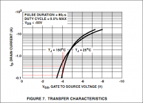
I am sure that his CCS MOSFET VDS for max ID sourcing is not at its stiffest region with his now transformer, still I am also sure that his VGS has gone up since he has set 0.37A than 0.16A he had been using before. If we quickly look up the IRFP9240's ID/VGS curve as it comes from a FAIRCHILD datasheet, although its a low resolution region we are interested at and no MOSFET sample is the same to its next, his loss of voltage drop across his setting resistor complies with the VGS increase scale I have traced out in red lines.
P.S. If he will go 1.3A hot rod as he aspires to an all out build he will be in the zero tempco area also. A CCS stability bonus.
P.S. If he will go 1.3A hot rod as he aspires to an all out build he will be in the zero tempco area also. A CCS stability bonus.
Attachments
Problem resolved
Hi Andrew T,
You were helping me trouble shoot about 5 months ago when I had to drop audio and attend to some other stuff. Well I finally got back and following the schematic-checking node voltages as you'd suggested found a reversed component C560. Cant imagine how I managed to overlook that so many times but all is better now and my output voltage are equal and opposite -10.4 and 10.1.
Ill step up to a 15v toroid now and be done with it.
Thanks very much for your help,
Fritz
Quote:
Originally Posted by Fritz View Post
.................Pair A
Vg -13.1 and 13.2
Vs -16.6 and 16.7
Vd -13.1 and 10.1?
Pair B
Vg -9.8 and 6.6 ?
Vs -13.1 and 10.1
Vd 0 and o.............
I am not allowed to edit the quote of your post !
So I will repeat it here - edited:
A Series FET = CCS
Vg -13.1
Vs -16.6
Vd -13.1
B Shunt FET
Vg -9.8
Vs -13.1
Vd 0
CCS fet
Vgs = +3.5Vgs. OK
Vds = +3.5Vds, something not right.
Shunt FET
Vgs = +3.3Vgs, OK
Vds = +13.1Vds, OK
The series FET can operate with a low Vds, but this circuit does not use it that way.
Mark those voltages on your big schematic. Where does it look like it is going wrong? Is there short g to d? Measure Vdg at the FET PINs.
__________________
regards Andrew T.
Got it guys. At least now I got a better grasp of how the thing works. I m gonna work on the chassis now while I try to figure out what I m going to do for a transformer.
I have made a template out of MDF and I think I am satisfied with it.
Tomorrow I m routing the proper wood. Don t you hate it some times that people are sleeping at 1am?
I have made a template out of MDF and I think I am satisfied with it.
Tomorrow I m routing the proper wood. Don t you hate it some times that people are sleeping at 1am?
I managed to work on the wood a bit today. I hope you don t mind the non-electonic nature of my post
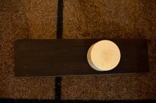
Here is a photo of how the front will look
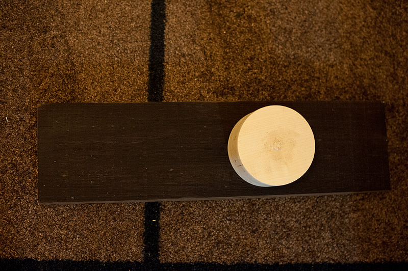
The chassis will be made out of 2,5cm thick planks of wenge (roughly 45x 34x15cm final dimensions). Wenge is very beautiful and also very dense and heavy, making it very nice in vibration damping as well. I have used it in the past and results were excellent both sonically and cosmetically.
The mother of all knobs was routed out of a 5,5cm thick maple plank and it's 9cm in diameter. Again, the huge size has excellent results in damping vibrations from the pot. With it attached I cannot even feel the clicks of the encoder.
The truth is that it is kind of huge, so I will also route about 1,5cms out of the wenge where the knob will be, so that it sinks into the surface there giving it a very nice look, both by hiding its end into the wenge and by reducing how much it protrudes from the chassis.
The final touch on the front will be a single white led on the left
Here is a photo of how the front will look
The chassis will be made out of 2,5cm thick planks of wenge (roughly 45x 34x15cm final dimensions). Wenge is very beautiful and also very dense and heavy, making it very nice in vibration damping as well. I have used it in the past and results were excellent both sonically and cosmetically.
The mother of all knobs was routed out of a 5,5cm thick maple plank and it's 9cm in diameter. Again, the huge size has excellent results in damping vibrations from the pot. With it attached I cannot even feel the clicks of the encoder.
The truth is that it is kind of huge, so I will also route about 1,5cms out of the wenge where the knob will be, so that it sinks into the surface there giving it a very nice look, both by hiding its end into the wenge and by reducing how much it protrudes from the chassis.
The final touch on the front will be a single white led on the left
Attachments
The your choice stuff is about parts ''quality'' not values. We can't recommend pricey parts to everybody. It works without electrical differences from generic to ''Rolex''.
There are options between high CCS, low CCS, reg only, full buffer. Matched fets are the quad behind the relay.
Big diodes and big 10W 10R resistors and big heatsinks make it hotrod. Small diodes, 47/47R small resistors, mini heatsinks make it regular.
Tea had a blog I think showing the prototype constructed.
Blue DCB1 is not a kit, its a better board for a very extensively discussed project. Has its options, and its very easy to figure. All builders are happy to explain specifics.
Wonder why 10 ohm resistors did not make it hot at all ?
Which bit do you want to get "hot"?
The 10W resistor, or the Shunt mosFET, or the CCS mosFET, or the PCB traces, or ...... ?
The shunt mosfet or just something .As I remember nothing got Hot at all. It is in our club and for some reason we have not used it yet. It was intended for use with bad designed Audio Note dacs.
Use 2.2R 10W resistors and it will get hot. Those MOSFETS are 0.83 RΘJC devices included to can go in amperes constant current if chosen so. Use green 2V+ leds in the triplets to aid voltage drop over the Rset as the Vgs nears the total Vf with stronger current choices. Have your K probe or laser aiming thermometer handy to check your sinks are sufficient.
Use 2.2R 10W resistors and it will get hot. Those MOSFETS are 0.83 RΘJC devices included to can go in amperes constant current if chosen so. Use green 2V+ leds in the triplets to aid voltage drop over the Rset as the Vgs nears the total Vf with stronger current choices. Have your K probe or laser aiming thermometer handy to check your sinks are sufficient.
Maybe I will try that in the New year ! We have to listen to it first to exsperience if there is need for that.
Hi Tea-Bag,
any boards and kits left?
Regards,
Should I go to China?


- Home
- Source & Line
- Analog Line Level
- Salas hotrodded blue DCB1 build