This is true. The OPTs are PTs so they have CSA certification (TuV, UL, etc) but the audio input transformers have never been approved to withstand power systems by CSA (Product Certification & Standards Development - CSA Group) - I think CSA used to be a government agency.
http://catalog.triadmagnetics.com/asset/ty-250p.pdf is the input coil. Also I was mistaken... 1500V, not 2kV.
http://catalog.triadmagnetics.com/asset/ty-250p.pdf is the input coil. Also I was mistaken... 1500V, not 2kV.
Last edited:
Has been done in the past. If done now (here at least) no insurance company will help out when things go wrong. Problem is that it only works OK/safe when one always connects L and N to the right wires which is not guaranteed with for instance Schuko sockets. If not for the end user then the tech that services/repairs such an installation is in straight danger. One might argue that transformers work both ways as well so when things go wrong on the AC part of things an unsafe voltage can occur at the primary/input side of transformers. This is often forgotten, also in industrial installations. Needless to say that it also will never be approved.
As it is solely price driven it makes no sense (P goes before S and Q). Big no no, plain wrong engineering.
Usually the autotransformer follows. I have recently seen a 25 kV version of it. Nothing but trouble and forbidden since ages for consumers here.
As it is solely price driven it makes no sense (P goes before S and Q). Big no no, plain wrong engineering.
Usually the autotransformer follows. I have recently seen a 25 kV version of it. Nothing but trouble and forbidden since ages for consumers here.
Attachments

Last edited:
Don´t like the idea..One is turning the clock back to the 1940-50´s when it was common to have the chassis connected to one side of the mains, first checking it wasn´t live !...with equipment insulation solely relying on a Bakelite knobs and cabinet. Don´t try anything modern connecting unproofed headphones to live circuitry ! Also many input transformers are Bifilar wound to reduce leakage inductance issues, this directly leads to lower breakdown voltages.
Some of us lived in the past with lethal ways, even myself as a G8 HamR often flouted the rules by first checking that the chassis was connected on the neutral side then the RF earth connected to the plumbing. In the MiddleEast this dangerous practise is still done.
There are no earth leakage trips to avoid this scenario to protect the user.
Stay in one piece.
Input transformers - the good ones like Jensen - are just for breaking ground loops. I wouldn’t count on them to keep your hands off 120 or 240.
I have seen at least one series of touring-grade powered subwoofers that use non isolated power supplies - running the internal class D amplifier directly off the PFC 390 volt rail with a buck converter for regulation. They use an optoisolator to couple in the audio after it’s already PWM’ed. Those can handle up to 8 kV. You’re not going to get audiophile performance out of an opto in the analog domain, where you would need it to isolate a tube amp. Digital, it’s possible. These amps would be a real pain in the *** to service - I don’t think I’d even try. Just throw it out and order a new amp module for two grand.
I don’t consider power transformers for tube amps to be a cost burden anyway. You ALWAYS pay a lot more for the output transformer and you can’t get away without that, unless you’re playing with exotic tubes. When you start doing that you throw cost out the window. Power trafos in the 100 to 400 watt range are easy to wind, and I can always find donor cores good for 60 Hz operation. When I built the “big” one with the 6 6550’s I used four off the shelf Anteks to make all the power supplies, and they all added up to half what the 1650W cost. Even if I used a tripler directly off the line to power the main B+, I still would have needed the other two smaller power trafos, and the input ground loop breaker - saving a whopping $120 on two 4T430’s per channel. Would that be worth getting thrown across the room a few times during project development? I don’t think so.

Been there, built that, a long time ago, 1969 or 70 I think.
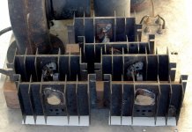
I ran across a huge heat sink with boxer fans on each end, and 4 isolated rails with 6 each 2N3773 transistors on each rail in a military scrapyard. I wired the transistors as 2 parallel banks of 12, each with it's own emitter resistor. I then wound an input / driver transformer on the dual winding bobbin and core from a Radio Shack filament transformer. There was the input winding on one half of the bobbin, and the bifilar drive windings on the other half. I used the totem pole output topology popular with germanium transistor amps in the mid to late 60's. The power supply was rectified and filtered wall outlet.
All was encased in a wooden box with grounded metal screens for airflow. Military connectors from the same scrapyard that supplied the heat sink were used for speaker outputs.
We drove this thing with a solid state Fender PA amp, or a Marshall tube amp depending on the desired use. It made an untold amount of power which was limited only by how many speakers you connected to it, and the size of the breaker feeding it.
I gave this to a schoolmate who was in a locally touring rock band at the age of 17. He was a very smart kid who fully understood the risks and safety measures involved in using it. There was the typical "three neon lamp" outlet safety tester built into the box. He was still using it the last time I saw them, in 1973 or 1974. Even then he still had the "loudest PA system on the planet."
Would I do this today? NO. There are too many people who THINK they understand electrical safety because they watched a Youtube video or two. Some unfortunately will learn the hard way that they don't.
At the time I built this there, were at least two commercial guitar amps using a similar design and running a pair of Delco high voltage transistors directly from rectified line voltage. The one that I got to repair was a Danelectro brand. It was a combo amp and used a pair of 16 ohm speakers in series. It flamed out in spectacular fashion when the owner tried to wire up some external 8 ohm speakers. The Delco transistors were no longer made, so I had to add a power transformer and convert the thing to a conventional guitar amp design.
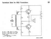
I enclosed the typical totem pole schematic from an old RCA transistor manual. Mine did not use split supplies, it had a large cap in series with the speaker.
I ran across a huge heat sink with boxer fans on each end, and 4 isolated rails with 6 each 2N3773 transistors on each rail in a military scrapyard. I wired the transistors as 2 parallel banks of 12, each with it's own emitter resistor. I then wound an input / driver transformer on the dual winding bobbin and core from a Radio Shack filament transformer. There was the input winding on one half of the bobbin, and the bifilar drive windings on the other half. I used the totem pole output topology popular with germanium transistor amps in the mid to late 60's. The power supply was rectified and filtered wall outlet.
All was encased in a wooden box with grounded metal screens for airflow. Military connectors from the same scrapyard that supplied the heat sink were used for speaker outputs.
We drove this thing with a solid state Fender PA amp, or a Marshall tube amp depending on the desired use. It made an untold amount of power which was limited only by how many speakers you connected to it, and the size of the breaker feeding it.
I gave this to a schoolmate who was in a locally touring rock band at the age of 17. He was a very smart kid who fully understood the risks and safety measures involved in using it. There was the typical "three neon lamp" outlet safety tester built into the box. He was still using it the last time I saw them, in 1973 or 1974. Even then he still had the "loudest PA system on the planet."
Would I do this today? NO. There are too many people who THINK they understand electrical safety because they watched a Youtube video or two. Some unfortunately will learn the hard way that they don't.
At the time I built this there, were at least two commercial guitar amps using a similar design and running a pair of Delco high voltage transistors directly from rectified line voltage. The one that I got to repair was a Danelectro brand. It was a combo amp and used a pair of 16 ohm speakers in series. It flamed out in spectacular fashion when the owner tried to wire up some external 8 ohm speakers. The Delco transistors were no longer made, so I had to add a power transformer and convert the thing to a conventional guitar amp design.
I enclosed the typical totem pole schematic from an old RCA transistor manual. Mine did not use split supplies, it had a large cap in series with the speaker.
Attachments
Last edited:
1600 watts into 2 ohms. With a 2kVA isolation transformer, this drops to 1300 watts (l have done this exercise). You’d need a 5kVA or more for it to keep up. For this application, think old Square-D enclosed dry types. Too bad you can’t just go to Skycraft and pick one up for a song anymore. They got them in *regularly* back in those days - I had a couple fives and a 10 - using them for actual isolation purposes, including bypassing a bad neutral at one venue that regularly caused PA system burnouts. Run off 240 and make your own neutral and it runs all night WITHOUT blowing up your Phase Linear.
It is however within the SOA of the 12 2N3773’s so it will run all day on 2 ohms, unlike Phase Linears. You do need to select them for voltage, because the line may go high. Most Motorolas will take 200+ - that’s what the Peavey SJ6343 in the CS800 was. That would have been THE loudest PA system on the planet - you absolutely couldn’t get a regular amp that could do more.
It is however within the SOA of the 12 2N3773’s so it will run all day on 2 ohms, unlike Phase Linears. You do need to select them for voltage, because the line may go high. Most Motorolas will take 200+ - that’s what the Peavey SJ6343 in the CS800 was. That would have been THE loudest PA system on the planet - you absolutely couldn’t get a regular amp that could do more.
Been there; done that. First audio amp I designed used two 35W4's to form a PTX-less full wave power supply to run a 50C5 final (I was 10 ATT). There can still be problems with a, if not hot, certainly a warm, chassis. That third wire neutral isn't a ground if the three phase distribution goes out of balance. This is why you see four wires these days. Two hot for the +/-120V biphase, one connected to the neutral, and the fourth connected to an actual earth ground.Never heard of a non-isolated audio amp running directly off the bi-phase before.
Not sure I want to, either.
I enclosed the typical totem pole schematic from an old RCA transistor manual. Mine did not use split supplies, it had a large cap in series with the speaker.
Interesting that, the yopology is nearly identical to that of a Class D RF amp.
The circuit I showed, often called a "totem pole" design was pretty common in the mid 60's. I learned about it when I built a Heathkit AR13 receiver kit for my neighbor when I was 12 (1964). I saved up enough money to buy one of those three winding driver transformers at the Heathkit store and started making my own amps, mostly for guitar as I only had one transformer. Almost every amp I saw that used that circuit as a repair guy in the late 70's used 2N2147's. As a kid I used what was free, those big old TO-36 "doorknob" transistors found on the back of early 60's car radios. My variable power supply was a DIY rectifier and filter connected to a big Lionel train transformer. With the transformer at "full speed" I got about 24 volts which was about the limit on those "free" transistors. Want the guitar amp louder? Then keep connecting more speakers until it blows up, fix it, then remove the lousiest speaker. Most of my speakers came out of old radios, TV's, and stuff. Only the strong survived.....my guitar playing.
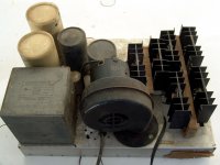
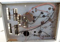
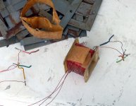
A few years later I was winding my own driver transformers and connecting up multiple pairs of transistors to them. About 50 years after its construction I found one of my early creations as I was planning to move everything I owned out of Florida. This was made in 1967 or 1968 using only a hand drill and a nibbling tool. The driver transformer was wound on the core of a fried Radio Shack filament transformer. The 6 output transistors were a salvage yard find, sold as "2N3055s." Whatever they really are remains a mystery, but these ran for years on a B+ supply of just over 100 volts, note the labels from my "HFE matching" exercise. I saved the transistors and heat sinks, and tossed the rest, as it was not worth moving. It had been left in a shed that was decapitated by hurricane Wilma. Smoke happened when I jumped the blown fuse and plugged it in outdoors. One of the big electrolytics spewed.
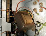
I took my DIY driver transformer apart to see what I did when I was 15. Yes, that is masking tape after nearly 50 years. I used the same stuff when winding new secondaries on the primaries of transformers removed from dead TV sets. Cheap or free transformers for solid state amps were not easy to find in the 60's and you can only connect so many random non-identical filament transformers together before the weakest one fries. I would not do any of this stuff today, but 15 year old kids are invincible in their own minds, right? Unfortunately two of my friends did not live long enough to finish high school, but drugs and stupidity were involved there.
The BIG amp with 24 X 2N3773's used the same circuit and DIY transformer. At least it was a dual bobbin transformer.
A few years later I was winding my own driver transformers and connecting up multiple pairs of transistors to them. About 50 years after its construction I found one of my early creations as I was planning to move everything I owned out of Florida. This was made in 1967 or 1968 using only a hand drill and a nibbling tool. The driver transformer was wound on the core of a fried Radio Shack filament transformer. The 6 output transistors were a salvage yard find, sold as "2N3055s." Whatever they really are remains a mystery, but these ran for years on a B+ supply of just over 100 volts, note the labels from my "HFE matching" exercise. I saved the transistors and heat sinks, and tossed the rest, as it was not worth moving. It had been left in a shed that was decapitated by hurricane Wilma. Smoke happened when I jumped the blown fuse and plugged it in outdoors. One of the big electrolytics spewed.
I took my DIY driver transformer apart to see what I did when I was 15. Yes, that is masking tape after nearly 50 years. I used the same stuff when winding new secondaries on the primaries of transformers removed from dead TV sets. Cheap or free transformers for solid state amps were not easy to find in the 60's and you can only connect so many random non-identical filament transformers together before the weakest one fries. I would not do any of this stuff today, but 15 year old kids are invincible in their own minds, right? Unfortunately two of my friends did not live long enough to finish high school, but drugs and stupidity were involved there.
The BIG amp with 24 X 2N3773's used the same circuit and DIY transformer. At least it was a dual bobbin transformer.
Attachments
Gloves are a safety requirement in other trades but they do not appear to be flexible enough for the kind for toys we work on. Do any fellow members have a recommendation for a glove (brand/model) suitable for work on tube equipment up to 600V. I have never used them but with advancing age I find myself a little less secure in my movements.
These ones are flexible and rated amoungst the best...
https://www.atg-glovesolutions.com/en/maxiflex/maxiflex-ultimate/34-874
A list: https://electricalschool.org/best-w...n/?nab=0&utm_referrer=https://www.google.com/
https://www.atg-glovesolutions.com/en/maxiflex/maxiflex-ultimate/34-874
A list: https://electricalschool.org/best-w...n/?nab=0&utm_referrer=https://www.google.com/
Much appreciated.These ones are flexible and rated amoungst the best...
https://www.atg-glovesolutions.com/en/maxiflex/maxiflex-ultimate/34-874
A list: https://electricalschool.org/best-work-gloves-for-electrician/?nab=0&utm_referrer=https://www.google.com/
Having worked with high voltage tube broadcast transmitters, one with 40,000 volts @ 4 amps, I would say don't handle high voltage when tired and stay alert. The tip about voltage jumping through a screw driver handle is a good example of why you should not be touching active high voltage with anything. Mistakes are easy to make, always condsider capacitors are charged. You have not lived until you have to discharge a 10,000 volt capacitor or hear 40,000 volts arc across a three foot insulator (dust on the insulator).
There are not a lot of accounts of DIY electrocution, especially in electronics (as opposed to house-wiring).
But there was a real tragedy in 1935. Mom called her sons every night on a long-range ham radio. While the two accounts I found differ slightly, apparently she did the change-over from code to voice without proper shut-down or discharge. 3,200 Volts is not unusual in powerful ham transmitters.
But there was a real tragedy in 1935. Mom called her sons every night on a long-range ham radio. While the two accounts I found differ slightly, apparently she did the change-over from code to voice without proper shut-down or discharge. 3,200 Volts is not unusual in powerful ham transmitters.
Attachments
We use gloves like these around our 480VAC three phase 100A circuits.Much appreciated.
https://www.fullsource.com/pip-155-...umpzwRIbU4hcv1Q7iWDyTh79GZtg9MaxoCBvEQAvD_BwE
With 480 3 phase, you'd likely want full frontal protection to keep from being fried from head to foot if a panel decides to explode - it happens all too often.
A post doc once blew up a large Variac right in front of me, when he turned it on
after connecting it wrong. Quite spectacular.
- Home
- Amplifiers
- Tubes / Valves
- Safety Practices, General and Ultra-High Voltage