Thank's!SA2015 using IRFP240/IRFP9240 should work with 2 pairs too when you lower the rail voltages. If you drive only 8R loads you can safely omit 1 pair of MOSFETs.
BR, Toni
")
I realized two amplifiers class a (2x15W), one equipped with red Keratherm and the other of silicon gray pad but both without any grease and no problem so far. However, the red Keratherm is more efficient.I amn't sure what is the right,i see many commercial products using rubbers+paste,other not.
I will try to measure in my SX(Bonsai) amplifier where rubbers and no paste has been used.
I realized two amplifiers class a (2x15W), one equipped with red Keratherm and the other of silicon gray pad but both without any grease and no problem so far. However, the red Keratherm is more efficient.
Will be useful if you can measure this with silicon gray pads .
Two measurements,one direct on transistor body and another on the heatsink.
Ok thimios, I do that in the day.Will be useful if you can measure this with silicon gray pads .
Two measurements,one direct on transistor body and another on the heatsink.
I think the temperature readings will be quite high because it is extremely hot right now in France.
your latest temp reading look a bit odd.
The bolt 57C which is thermally insulated from the transistor and yet thermally coupled to the heatsink 51C is very hot.
The air cooling of the top surface of the transistor 53C would indicate that Tc is probably a little bit higher than this.
The 51 for the heatsink adjacent to the transistor seems a bit high taking account of the temp diff from Tc to Ts across the insulator.
Yet the heatsink a little further away is way down @ 41C. Something quite odd.
Could you be using an IR temp meter that is reading a wide beam and picking up on other surfaces at different temps?
I used an infra red pointer for measurements but they are quickly different depending on the location and I may not have been accurate enough.
It should be noted that this amplifier is actually a class A and that this seems to me quite normal high temperature.
I will take action again, taking care to measure the sites I will target.
Thanks Andrew.
It should be noted that this amplifier is actually a class A and that this seems to me quite normal high temperature.
I will take action again, taking care to measure the sites I will target.
Thanks Andrew.
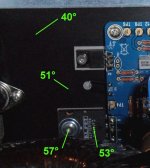
Here are the temperature readings after stabilization, the quiescent currents are 1A and the temperature of the room is 22 °.
With Keratherm red heat transfer is faster. With the gray pads I noticed that this process was slower.
Regard's
Thanks Project16!your latest temp reading look a bit odd.
The bolt 57C which is thermally insulated from the transistor and yet thermally coupled to the heatsink 51C is very hot.
The air cooling of the top surface of the transistor 53C would indicate that Tc is probably a little bit higher than this.
The 51 for the heatsink adjacent to the transistor seems a bit high taking account of the temp diff from Tc to Ts across the insulator.
Yet the heatsink a little further away is way down @ 41C. Something quite odd.
Could you be using an IR temp meter that is reading a wide beam and picking up on other surfaces at different temps?
So it's a difference of about 6°C between bolt and heatsink,in my case is a bit higher.
Andrew,i dont think that bolt is thermally insulated from the transistor.
I confirmAndrew,i dont think that bolt is thermally insulated from the transistor.
The amplifier is currently working and: Humm the sound is fabulous!

http://www.diyaudio.com/forums/soli...ur-solid-state-pics-here-511.html#post5031437
I will take measurements within 1 hour and we will see the differences at the different points of measurement.
PS: Thimios I think I will realize the same amplifier as you but the bipolar version.
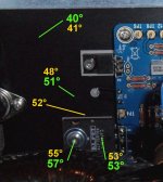
After one hour of operation, the readings appear to confirm the first (values in yellow). The outer fins of the heat sinks have a uniform temperature throughout the heatsink of 42 °.
The measurements are made with an infrared pointer for an ambient temperature of 22 °.
The measurements are made with an infrared pointer for an ambient temperature of 22 °.
Attachments
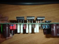
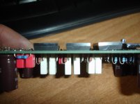
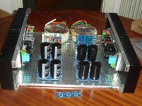
One chanell disassembled for mosfet replacement.
This one was the first built and wasn't built using matched mosfets.
Because of a big difference in the idle current of the center pair (168mA against 136mA other pairs),i decided to replace with matched pairs.
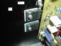
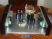
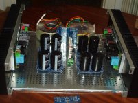
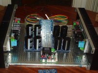
Now i have a dilemma, what is the preferable way for mosfets mounting?
As in picture 1 or in picture 2.
Can the first way,given more room to mosfets, ensures better cooling conditions?
Is it a danger for instability?
This one was the first built and wasn't built using matched mosfets.
Because of a big difference in the idle current of the center pair (168mA against 136mA other pairs),i decided to replace with matched pairs.
Now i have a dilemma, what is the preferable way for mosfets mounting?
As in picture 1 or in picture 2.
Can the first way,given more room to mosfets, ensures better cooling conditions?
Is it a danger for instability?
Attachments
Last edited:
Let's wait Toni's opinionPersonally I think image 1 represents a better layout of the transistor but the problem is now to reposition all the others.
But let's wait to know what the most technician in this field think.
Last edited:
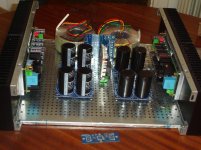
Don't solder the mosfets. just mount pcb with unsoldered mosfets. adjust and mount mosfets. solder now mosfets. unmount again, add 6 lytics and add isolation pads. final mount.
The shorter the pins the better the stability. If using 5mm distance holders it is optimal. cooling doesn't better if you add more distance...
The shorter the pins the better the stability. If using 5mm distance holders it is optimal. cooling doesn't better if you add more distance...
Last edited:
Exactly as before!Don't solder the mosfets. just mount pcb with unsoldered mosfets. adjust and mount mosfets. solder now mosfets. unmount again, add 6 lytics and add isolation pads. final mount.
The shorter the pins the better the stability. If using 5mm distance holders it is optimal. cooling doesn't better if you add more distance...
Thanks Toni.
Yes,i see yours,i want to eliminate the main voltage <<travel>>.Hint: MCU board and inrush current control pcb can be stacked ...
The shorter a.c the better!
I wonder if a second steel case(inside amplifier case) for all the power supply parts is a good idea.
Last edited:
- Status
- This old topic is closed. If you want to reopen this topic, contact a moderator using the "Report Post" button.
- Home
- Amplifiers
- Solid State
- SA2015 V-MOSFET Builders