This is one of many in this thread and other threads. Byrtt may be able to show you more or search for posts by him.
http://www.diyaudio.com/forums/multi-way/277691-s-harsch-xo-7.html#post4429283
Hi xrt971,
That post (No.67) only refers to target responses generated via Jriver and REW. It says nothing about recording music through a Harsch Xover implemented in a miniDSP. Maybe Byrtt can help link me to it.
Peter
Hi xrt971,
That post (No.67) only refers to target responses generated via Jriver and REW. It says nothing about recording music through a Harsch Xover implemented in a miniDSP. Maybe Byrtt can help link me to it.
Peter
Those REW tests is done by a physical hardwire loop at sound cards I/O in mono either left or right track. Trick is JRiver have a Virtual soundcard which when pointed to from other programs (REW) as output device routes all sound through JRivers DSP engine, and inside this DSP engine there is unbelievable power to make whatever one want be it IRR/FIR filters split signals and mix again including set local delays or phase shift on the splits before they sum again, and by that one can run the HARSH XO and check for right delays.
Haven't done test as you intend but above electric tests is so close, so here a proposal to how your intended recording task could be using just a cable plus software and a simple stereo sound card:
Play a track inside JRiver and in JRiver DSP at left channel set a XO HARSCH low pass filter and at right channel set a XO HARSCH high pass filter. Then hardwire loop sound cards stereo I/O and in real time record sound cards input with Audacity. This will give two tracks inside Audacity that just need to be mixed inside Audacity to represent the played track routed through a HARSCH XO. Do the same once more but without XO in DSP to have a reference track to compare with, so as we on reference track also get the signature from your sound cards I/O ADC/DAC amps and its IRR passband domain into the reference track. The playback track used must be mono and can be done example by edit real time routing/mix busses inside JRiver DSP or one could edit raw track inside Audacity to mono before the playback/record process.
If you not have a licenced JRiver their full featured trial version will run for 30 days, and the licenced one is allowed on two computers. Foobar is free and should be able to do same as JRiver, and Audacity is free.
Last edited:
Thanks Peter. And thanks for the plots. I agree that the delay might be tweaked a little. I will look at this further tonight and post what I find.Hi Pano,
A BW3 LPF works just as well as an LR4 LPF and as you say, possibly a little better!
Thanks Peter. And thanks for the plots. I agree that the delay might be tweaked a little. I will look at this further tonight and post what I find.
Are you going to try in practice or sims? Be good to get your listening impressions. Works best with non produced live performance recordings.
Hi Byrtt,
That sounds really neat stuff. Sounds like the basis for a great Blog or Article to teach mortals like myself how to do all that audio processing in the digital domain, very impressive!
You mentioned using Foobar, which is what I started out using. What I did was to generate the impulse response of the Harsch Xover, which I then plugged into foo_convolve.dll. This allowed me to play back any source material I wanted, but I had the feeling that this would not work for some members of DIYAUDIO, because of the time/effort in setting up and familiarising themselves with foobar.
This is the main reason why I took the approach described in post#93.
Members simply download a wav file containing the original and Harsch processed data and judge for themselves if they can hear the difference between them. The only thing I have to do is to take account of the overshoot during the recording process, which appears to be about 4-5dB and hopefully will not degrade the signal to noise ratio too much.
Peter
I was going to try both, but am finding it hard to do. I need LP and HP that allow the slopes needed. I no longer have my DCX crossover, so am trying to do it in software.Are you going to try in practice or sims? Be good to get your listening impressions.
I was going to try both, but am finding it hard to do. I need LP and HP that allow the slopes needed. I no longer have my DCX crossover, so am trying to do it in software.
Do it like Byrtt describes above with plugins in Jriver. Use left for low pass and right for high pass. Pick any slope you like with the DSP plugins. Actually a sound card and Jriver or foobar can get you into the DSP game for essentially no cost (in mono).
Pano,
Give me some hours and will get back with some usefull data for JRiver and the two different scenarios we want that is either pure electric or measured acoustic slope.
For the electric ones JRiver only have build in BW 1/2/4/6/8 order, but we can cascade and or combine BW's a shelf or PEQ that then form a LR or BESSEL filter.
For the real world measured acoustic filters the electric ones set in JRiver has probably nothing in common with the textbook acoustic slope and typical is build upon lower order electric and some shelf and PEQ to get the right textbook acoustic slope, therefor a target curve for the measurement program with the right textbook slope is a good helper and that can often be created in Rephase and imported to measurement program so we have a trace to steer our filtering for.
Right, thanks. I was not finding a direct way to get the filter slopes needed, so was looking for something like that.
Looking forward to seeing what you do.
This is part one covering the Electric textbook slopes in JRiver, another post will cover helper target slopes for acoustic filters:
Having the electric slopes inside a JRiver PEQ container is of big flexible help and powerfull because inside that container one is able to example split/mix/route busses in upstream part of the container, then add different complex filters going downstream and mix/route them again lower stream inside same container, think that gets harder or maybe impossible using some free 3. party VST plugins.
Problem is regarding electric textbook XO slopes JRiver only has BW 1/2/4/6/8 order build in.
Most will probably know to create LR slopes it takes two cascaded BW filters to create a LR, example BW1 in series BW1 gives a LR2 and BW2 in series BW2 gives a LR4 etc, so now we able to make above mentioned standard BW filters plus a handful LR filters created/based on the BW ones.
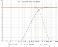
At this thread also needed is BES2 as seen at post one and Pano also need a BW3 which is not listed in JRiver. To create BES2 electric textbook filter at example 1000Hz cascade LR2 (2xBW1) at 1000Hz with PEQ at 1000Hz Q=0,58 +1,3dB, and to create BW3 electric textbook filter at example 1000Hz cascade BW2 + BW1 at 1000Hz + PEQ Q=0,84 +3,0dB set at 1000Hz.
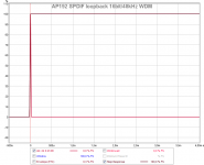
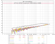
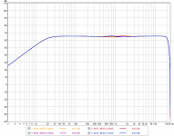
For documentation below is AP192 sound card hardwire loopback SPDIF I/O, REW send to JRiver virtual sound device and listen at AP192 input. Because of loop can't at present use ASIO driver and higher sample rate on the same computer therefor run java drivers 16bit/48kHz. As can be seen at legend the ones named "EF BES2" and "EF BW3" is third party free plugin from this link RS-MET and their traces is exactly overlayed with the two named "JR CASCADE xxx" which is made as written above. Two other pictures is just to document with no filters set in JRiver we should be able to trust result of sound stream from hardware and software.
Attachments
Last edited:
Nice work, Byrtt! Thank you for that. Will be interesting to see and hear what happens with the different filter approaches.
Unfortunately I don't have speakers that can use these filters at the moment, so will have to do mixing and headphone listening. Hope that someone else can test these on speakers. I doubt the 2 will sound much different.
Unfortunately I don't have speakers that can use these filters at the moment, so will have to do mixing and headphone listening. Hope that someone else can test these on speakers. I doubt the 2 will sound much different.
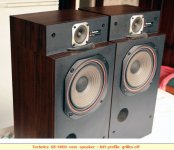
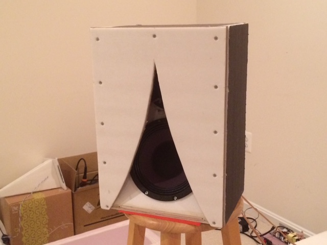
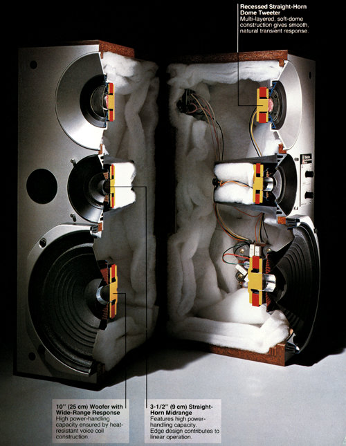
I think we are looking at a paper speaker like this time-aligned Technics SB-4000 to get transient perfect.
4th order 8" bass isn't hard, because that is what they do on simple second order electrical filters. And you can notch the Fs of a cone tweeter with a first or second order filter to get close to the 12dB/octave target slopes.
So we know what this speaker looks like.
4th order 8" bass isn't hard, because that is what they do on simple second order electrical filters. And you can notch the Fs of a cone tweeter with a first or second order filter to get close to the 12dB/octave target slopes.
So we know what this speaker looks like.
Attachments
Pano,
Agree they probably sound very close to original HARSH config BW4/BES2.
But also interesting if PLB will make a electric loop test, because if he record via his loop without filter and call that reference system bandpass, then record via electric standard HARSCH plus your suggested one plus other standard BW and LR with various order we can listen to their differences. Okay ther's no room mode as with real speakers and that textbook filter is probably in real world only achievable on design axis but we should be able to judge if phase shift from filter ruin the track compered the reference recorded one.
xrk971,
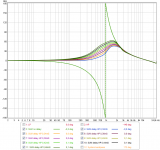
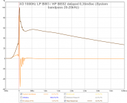
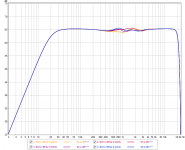
Here is wiggles, never zoom into this vertical range : ) as seen in first picture, see legends to understand, the 0,36mSec is the math Pano posted.
Picture 2 is Phase.
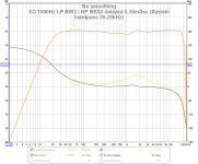
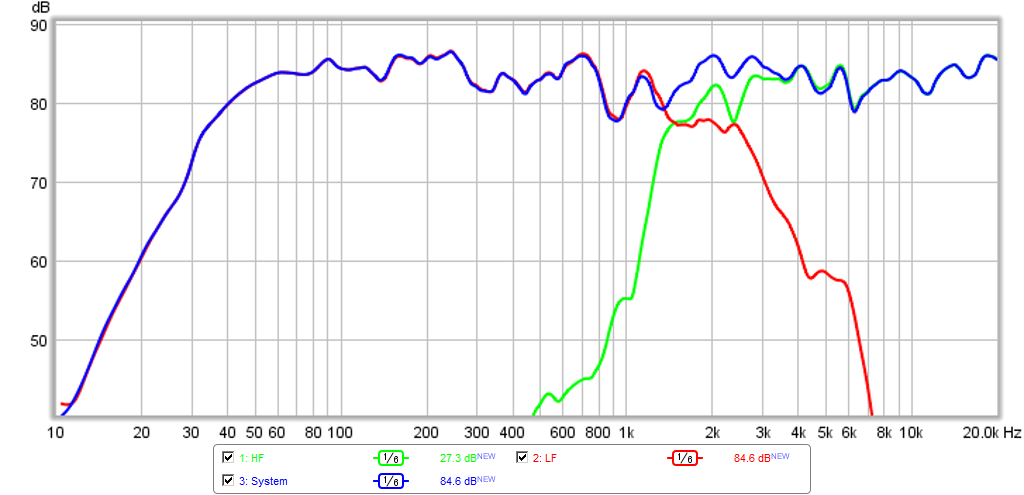
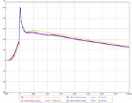
Picture 3 is much nicer 50 dB vertical range with 0,36mSec delay for tweeter and a system passband set at BW2 20-20kHz.
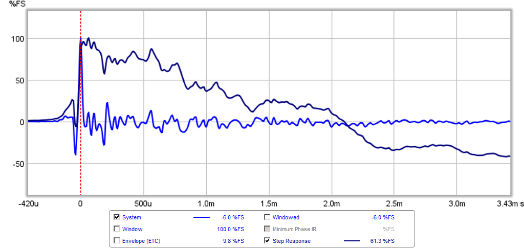
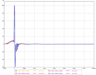
Picture 4 is IR/SR for picture 3.
Agree they probably sound very close to original HARSH config BW4/BES2.
But also interesting if PLB will make a electric loop test, because if he record via his loop without filter and call that reference system bandpass, then record via electric standard HARSCH plus your suggested one plus other standard BW and LR with various order we can listen to their differences. Okay ther's no room mode as with real speakers and that textbook filter is probably in real world only achievable on design axis but we should be able to judge if phase shift from filter ruin the track compered the reference recorded one.
xrk971,
Here is wiggles, never zoom into this vertical range : ) as seen in first picture, see legends to understand, the 0,36mSec is the math Pano posted.
Picture 2 is Phase.
Picture 3 is much nicer 50 dB vertical range with 0,36mSec delay for tweeter and a system passband set at BW2 20-20kHz.
Picture 4 is IR/SR for picture 3.
Attachments
Last edited:
Byrtt,
Thanks! Those curves look great - it is so clean as if you did it analytically by mathcad or something. Hard to believe those are actual measured electrical signals. Can you show how Pano arrived at the magic 0.36ms delay as the optimal based on equations only?
In Fig 3 with frequency response on larger scale, I see that there is dip that starts at 350Hz and this can have some benefits of removing the "thickness" in vocals to allow more discriminating monitoring of voices a la BBC's LS5/3A which has an intentional dip at 350Hz.
The SR doesn't look as good as the Harsch I don't think - there is a large overshoot peak.
I think now I understand how my Kazba coaxial managed to have a SR that looks something like this when I set electrical as LR2 on both LP and HP. The natural fall off and the electrical LR2/LR2 probably made some asymmetric slopea. Then when combined and the natural acoustic delay provided by the recesses coaxial driver arrangement, it put a delay on the tweeter and it worked out to be quasi transient perfect. I wonder if this may be perhaps why LR2 XO's may prove to be so effective with coaxials? Oh, you have to keep postitive polarity on both.
http://www.diyaudio.com/forums/full...zba-dipole-k-aperture-z-baffle-dipole-19.html
I think we are looking at a paper speaker like this time-aligned Technics SB-4000 to get transient perfect.
4th order 8" bass isn't hard, because that is what they do on simple second order electrical filters. And you can notch the Fs of a cone tweeter with a first or second order filter to get close to the 12dB/octave target slopes.
So we know what this speaker looks like.
They look good have you measured if they transient perfect ab fabric or modded them to be there.
That 2in setback reminds me of the 8in RS225-8 and 3in 10F/8424 that Byrtt and I worked together on for a 1st order electrical XO that was transient perfect. If the Technics was indeed going after a 4th order LP and 2nd order HP, a la Harsch, then a 2in setback for tweeter would say that the acoustic XO is circa 3400Hz. I wonder where the XO was for this speaker?
Check out these other phase linear (transient perfect) speakers from Technics (horns and waveguides to achieve time alignment) - beautiful cutaway. They don't do that kind of stuff anymore. Seems these have XO's in the 3k to 4k range.
Technics SB-X50 on thevintageknob.org
Check out these other phase linear (transient perfect) speakers from Technics (horns and waveguides to achieve time alignment) - beautiful cutaway. They don't do that kind of stuff anymore. Seems these have XO's in the 3k to 4k range.
Technics SB-X50 on thevintageknob.org
Attachments

Last edited:
Byrtt,
Thanks! Those curves look great - it is so clean as if you did it analytically by mathcad or something. Hard to believe those are actual measured electrical signals. Can you show how Pano arrived at the magic 0.36ms delay as the optimal based on equations only?.....
Some of the clean think come from the dialog box after push "Capture" icon, in that dialog box there's a default image width botton that always need to be pushed to have fonts and traces to be as sharp as possible in plots and in a way i wonder why it don't optimize image by itself.
Pano posted below regarding delay.
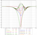
Below is BW4/BES2 verse BW3/BES2 inside a system bandwidth 20-20kHz, there is two delay examples for each slope setup see legend data.
Picture 4 filter effect looks good when vertical range is set a whoopee 160dB scale from -50dB-110dB as datasheet for A12P.
Interesting approach. Thanks for posting, I read the paper.
Possibly - by using the same 2nd order Bessel HP with a 3rd order Butterworth LP, you can achieve very similar results. Maybe slightly better. But in that case delay = (1/fc)*0.36
Anyone try that?
Attachments
- Home
- Loudspeakers
- Multi-Way
- S. Harsch XO