Legis,
Glad you are taking a look at absolute phase in your setup. Byrtt is correct in that the Step Response plot appears to show additional delay needed. In Synergy, this delay should be naturally provided by the relative physical offset of the drivers and should be quite close naturally. It may be that since your mids are from a large 15in bandpass injection chamber - there may be additional delays there. The plot indicates another 750usec of delay on tweeter should give you much better snap than you hear now. Yes, it does indeed make a difference which way the CD diaphragm pushes. If I recall - your CD has 2nd order high pass around 600Hz? Try applying 4th order BW low pass on woofers (or mids). The 600Hz XO would indicate a 714usec delay to tweeter is needed. If your inherent acoustic offset is about 35usec this would make sense and show that you can achieve a much tighter SR with a Harsch XO.
Glad you are taking a look at absolute phase in your setup. Byrtt is correct in that the Step Response plot appears to show additional delay needed. In Synergy, this delay should be naturally provided by the relative physical offset of the drivers and should be quite close naturally. It may be that since your mids are from a large 15in bandpass injection chamber - there may be additional delays there. The plot indicates another 750usec of delay on tweeter should give you much better snap than you hear now. Yes, it does indeed make a difference which way the CD diaphragm pushes. If I recall - your CD has 2nd order high pass around 600Hz? Try applying 4th order BW low pass on woofers (or mids). The 600Hz XO would indicate a 714usec delay to tweeter is needed. If your inherent acoustic offset is about 35usec this would make sense and show that you can achieve a much tighter SR with a Harsch XO.
Legis,
Glad you are taking a look at absolute phase in your setup. Byrtt is correct in that the Step Response plot appears to show additional delay needed. In Synergy, this delay should be naturally provided by the relative physical offset of the drivers and should be quite close naturally. It may be that since your mids are from a large 15in bandpass injection chamber - there may be additional delays there. The plot indicates another 750usec of delay on tweeter should give you much better snap than you hear now. Yes, it does indeed make a difference which way the CD diaphragm pushes. If I recall - your CD has 2nd order high pass around 600Hz? Try applying 4th order BW low pass on woofers (or mids). The 600Hz XO would indicate a 714usec delay to tweeter is needed. If your inherent acoustic offset is about 35usec this would make sense and show that you can achieve a much tighter SR with a Harsch XO.
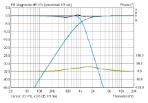
The mids' acoustic low pass is quite sharp, which is propably the source of the delay.
In SR it can be seen that the midwoofers start to step little before than the comp driver (around 0,4ms before) but the step of the woofers is "sluggish" to rise due to the restricted bandwidth/low xo-point (low freqs are slower
") ) and sharp acoustical xo'ing.
) and sharp acoustical xo'ing. I don't use any passive xo for the mids (just the acoutical), keeping things simplistic and SET friendly. Need to start up Xsim for the new setting, if something could be done to get the steps little bit closer together.
In synergy and other coaxials the time coherency is nice feature since the step response is ~the same no matter which angle you measure the speaker. With non-coaxials the time coherency is more "imaginary" and happens more or less perfectly only in one point of space.
Last edited:
Geddes put some special stuff in front his CD, think of this because X mentioned a 3d printer could be used to print some ala that over at Onni's thread. Would special 3d printed pattern present sound waves a longer distance and thereby delay sound from JBL driver in Legis build.
xrk971, enjoying this thread very much. I was curious about polarity for the two way Harsch transient perfect filter. Seems to be positive for time-aligned?
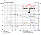
Don't think too hard about this at all, because it's an issue that I came across with time-aligned series filters, and not transient perfect because no 90 degree quadrature I think. But good phase alignment often goes hand in hand with 3dB peaks at crossover or a mexican hat shape. A big takeaway from your ideas here, is that flat frequency response is not compulsory or always desirable.
I'll try some of this. 4th order bass and second order tweeter...
Are the drivers' phases in 90 degree quadrature at crossover?
Attachments
TBH, I'm still a bit confused about the half wavelength time delay, but I think it's about 45 degree phase difference at crossover. Somewhere between -6dB phase aligned and -3dB quadrature aka 90 degrees butterworth style.
Because it looks like about -4dB. Looks like Harsch is saying place the tweeter acoustic centre half a wavelength back from the woofer's acoustic centre if you're not doing delay stuff. That's UNUSUAL!
Because it looks like about -4dB. Looks like Harsch is saying place the tweeter acoustic centre half a wavelength back from the woofer's acoustic centre if you're not doing delay stuff. That's UNUSUAL!
Attachments
Last edited:
Sys7:
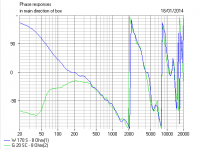
Polarity is all positive, and the half cycle delay gives a 45 deg phase shift at XO and helps to flatten the 3dB bump to several smaller bumps (squiggles). You know you have it right when the combined response dips slightly below the bass only and it wiggles up and down. The proof though is in the step response 'pudding'. You can hear it too very clearly on acoustic instruments.
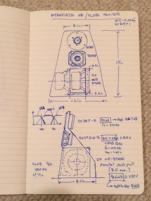
Over in Jeshi's thread on compact OB 3-way desktop monitors, my plan is to make this cute 3-way Harsch XO speaker:
Polarity is all positive, and the half cycle delay gives a 45 deg phase shift at XO and helps to flatten the 3dB bump to several smaller bumps (squiggles). You know you have it right when the combined response dips slightly below the bass only and it wiggles up and down. The proof though is in the step response 'pudding'.
You can hear it too very clearly on acoustic instruments.Over in Jeshi's thread on compact OB 3-way desktop monitors, my plan is to make this cute 3-way Harsch XO speaker:
Last edited:
If we go with a 12dB tweeter filter here, you recall the Snell/Audio Note Fs tweeter correction idea on a first order capacitor?
http://www.diyaudio.com/forums/multi-way/147632-classic-monitor-designs-17.html#post4358469
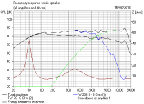
In fact that classic Audio Note design is not far off the Harsch target response, if not time-alignment. And it would be VERY easy to make the 8" woofer a bit steeper on rolloff with a notch around 7 kHz. Weird, eh?
http://www.diyaudio.com/forums/multi-way/147632-classic-monitor-designs-17.html#post4358469
In fact that classic Audio Note design is not far off the Harsch target response, if not time-alignment. And it would be VERY easy to make the 8" woofer a bit steeper on rolloff with a notch around 7 kHz. Weird, eh?
Attachments

Sys7,
That AN does have a remarkable resemblance to the Harsch BW4 and BES2 target curves. But the box has a flat baffle and there is no way to implement that kind of delay passively without either a stepped baffle or a waveguide to move that tweeter backwards. I think with careful selection of a woofer with a proper acoustic setback and a custom waveguide you can achieve time alignment with a passive Harsch. In fact that is one of my to do list items.
For low XO points where radiation from the back of a woofer is perfectly acceptable, flip the woofer around magnet out to buy yourself circa 50mm of delay. Ugly as hell but would probably work .)
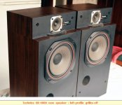
I don't think physical time-alignment is hard. It ends up looking like this Technics idea (below) with a big bass. And I'm not averse to flipping tweeter polarity.
But truly, xrk971, you are doing some excellent work here. It's all starting to fall into place for me. A half-wavelength at 3kHz is nothing really. A few centimeters.
But truly, xrk971, you are doing some excellent work here. It's all starting to fall into place for me. A half-wavelength at 3kHz is nothing really. A few centimeters.
Attachments
.....And I'm not averse to flipping tweeter polarity.....
You mean to get tweeter in same positive step polarity as woofer and not to cheat win some physical offset distance .....
don't think missed Steen Duelund would approve last as he wouldn't approve a recording that is inverted .If you flip tweeter polarity it is not quasi transient perfect anymore. It sounds different - basically a time aligned symmetric LR2 - not the same as a Harsch XO.
A few cm is not much but so many people are making flat baffle speakers. A waveguide helps a lot there and still keeps the apparent flat front baffle.
A few cm is not much but so many people are making flat baffle speakers. A waveguide helps a lot there and still keeps the apparent flat front baffle.
Interesting approach. Thanks for posting, I read the paper.
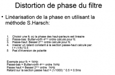
Possibly - by using the same 2nd order Bessel HP with a 3rd order Butterworth LP, you can achieve very similar results. Maybe slightly better. But in that case delay = (1/fc)*0.36
Anyone try that?
Hi Pano,
A BW3 LPF works just as well as an LR4 LPF and as you say, possibly a little better!
I’m not sure if you have already simulated this or not, but I ran a simulation myself comparing yours with the S. Harsch Xover as shown in the attached. As you can see, the step response is a little better compared to the S. Harsch Xover. Unfortunately, it still has significant overshoot on square waves though. Whether this is audible or not I don’t know. BTW, you’ll notice from the attached block diagram that I have tweaked the delay very slightly in order to minimise FR variations.
I have been thinking of constructing these types of filter using a miniDSP and making a few recordings for DIYAUDIO members to compare the original with the filtered version. These recordings would not be made with a microphone, rather, I would use one miniDSP channel for the bass/midrange and another for the tweeter and then electrically sum the two channels in a similar way as shown in the attached block diagram.
It would then be possible to apply an audio signal to the input of the miniDSP and record the summed output, thus avoiding the microphone/speaker response, room acoustic response and polar response differences etc.
This approach could obviously be used to test other types of Xover like BW3, LR2/4, and NTM etc.
However, I’m not sure how to post these audio files on DIYAUDIO, can you advice me on what is possible, like file size limits and types etc so that I could start another thread for it.
Peter
Attachments
Sys7:
Polarity is all positive, and the half cycle delay gives a 45 deg phase shift at XO and helps to flatten the 3dB bump to several smaller bumps (squiggles). You know you have it right when the combined response dips slightly below the bass only and it wiggles up and down. The proof though is in the step response 'pudding'.
Over in Jeshi's thread on compact OB 3-way desktop monitors, my plan is to make this cute 3-way Harsch XO speaker:
Have you calculated the resonance frequency for the woofer pair slot? This will strongly resonate and you will need to notch that out and should probably cross over at or below this frequency. Resonances are inherent to any system with a duct.
PLB
Check out the electrical experiments that Byrtt has done to look at XO's. Just as you suggest to avoid effect of the speaker. You can record the sound clips played through the miniDSP into a digital recorder such as a UCA 202. Once recorded convert to MP3. You can make up to 45sec long 320k MP3 to be small enough to upload.
Check out the electrical experiments that Byrtt has done to look at XO's. Just as you suggest to avoid effect of the speaker. You can record the sound clips played through the miniDSP into a digital recorder such as a UCA 202. Once recorded convert to MP3. You can make up to 45sec long 320k MP3 to be small enough to upload.
Have you calculated the resonance frequency for the woofer pair slot? This will strongly resonate and you will need to notch that out and should probably cross over at or below this frequency. Resonances are inherent to any system with a duct.
Yes, I normally model in Akabak but decided not to go with slot loaded OB due to limited bandwidth with slot. I went with Kazba with variable width slot to reduce resonance effect. The Kazba version is completed and in thread. Sounds very good actually.
http://www.diyaudio.com/forums/multi-way/280968-ob-compact-3way-nearfield-monitor-12.html
One significant problem with this Harsch approach is that the HP function on the tweeter has a very shallow rolloff. Typically using a first order HP function on a tweeter that has a low resonance frequency is a no-no. A first order crossover can allow the excursion to continue to INCREASE below the crossover frequency if the tweeter's response is not also falling off, which is the case with modern low Fs tweeters. This is why a second or higher order crossover is typically used.
In the old days the resonance frequency of tweeters could be 3kHz, and the excursion would level off on its own below Fs since it is a second order system. Adding a simple cap or first order network was sufficient, and this can be done in conjunction with the tweeter's own rolloff to make a third order acoustic slope. If Fs is 500Hz, the "leveling off" doesn't happen until 200Hz, by which time the excursion is getting too large for the tweeter's suspension. When you use a Harsch crossover with Fc at 1.5kHz (for instance), there is only first order attenuation on the excursion until resonance, which is much more than an octave below, and excursion can continue to increase below Fc.
I strongly suggest that anyone using the Harsch crossover should check the tweeter excursion.
The Harsch XO's I have done in practice used a full range driver as the "tweeter" so it was able to handle the excursions well. These were basically FAST approaches as described here:
A 2nd order electrical Bessel HPF was used in this case:
http://www.diyaudio.com/forums/full-range/273524-10f-8424-rs225-8-fast-ref-monitor.html
A 1st order Butterworth HPF was used in this case:
http://www.diyaudio.com/forums/full-range/280331-fr58ex-ac130f1-micro-fast.html
And in both cases, I did not have an excursion problem since the suspensions could handle 2.5mm xmax in both cases.
The one time I used a soft dome tweeter, it was in a 3-way with XO set at 4kHz and I used 2nd order Bessel HPF so excursion was not a problem. Even with 1st order I don't think it would have been an issue, although I never modeled the excursion for higher powers. I have heard that the Vifa soft dome tweeters used on the Dunlavy SC-IV sometimes do get blown out from high power "party level" use because they are 1st order electrical XO's. So yes, it would be wise to check one's tweeter excursion levels. In general, if using dome tweeters in a Harsch, set the frequency higher up rather than in the sub 2kHz range.
PLB
Check out the electrical experiments that Byrtt has done to look at XO's. Just as you suggest to avoid effect of the speaker. You can record the sound clips played through the miniDSP into a digital recorder such as a UCA 202. Once recorded convert to MP3. You can make up to 45sec long 320k MP3 to be small enough to upload.
Hi XRK971,
I guess I must have missed Byrtt's post and I can't seem to find it. Can you link me to it?
Peter
Hi XRK971,
I guess I must have missed Byrtt's post and I can't seem to find it. Can you link me to it?
Peter
This is one of many in this thread and other threads. Byrtt may be able to show you more or search for posts by him.
http://www.diyaudio.com/forums/multi-way/277691-s-harsch-xo-7.html#post4429283
- Home
- Loudspeakers
- Multi-Way
- S. Harsch XO