Byrtt thanks for taking the time to do up those charts. I don't have a clue how to put them to good use.
Will say don't get frustrated myself and probably also other diy members took quite some time to learn down the road from the pro's around here, you will get it some day and look back on having a good time being armed with knowledge to setup system with that modern miniDSP you invested money into, also there is more to this thing because even if we had your slopes going by now there is scientific good house curve to steal from a JBL published document to get sound closer to what studio guys often use as reference at a certain SPL out at listening position, its not a law to copy that curve and studio standards one can also set whatever house curve one like but its not bad try investigate how that JBL curve sounds to ones ears.
Have to admit i never worked with OB system, had it been two sealed pass bands could suggest very precise near field measurement method to base slope for both pass bands, ideal because we down at 80Hz where that very near field method is shining and can we have slopes as precise as possible all that is left is trim the two pass bands SPL level right and find the right numbers to delay mid-tweeter relative to woofer and the rest is up to you how much nit piking you offer and driver accept to smooth out mid-tweeter as frq goes up from its XO point.
Can see Nelson Pass member profile is not setup to receive PM so lets hope he will PM you, or search the web if there is some other contact links.
Have a laugh but have to do some washing right now, but will get back with some basic how to do steps.
Last edited:
Not frustrated at all on my side. The speakers sound wonderful. I have nothing to compare them to outside my house. Took me 60 hours just to learn how to set up the Mini dsp just so I could take measurements. May take much longer to put it to good use. I made 20 or so measurements this morning moving the speakers here and there. finally settled on a spot where measurements didn't very much. I've spent time changing crossover points, messing with delay, speaker output, and changing EQ filters using the auto method. It's all good. Time is on my side. Can't thank everyone enough for there patience.
Byrtt thanks for taking the time to do up those charts. I don't have a clue how to put them to good use.
Sorry forgot this one and think you mean the two multiple XDir simulations for vertical summation, it is so that to get a error free summation in XO region or can we say same dispersion in XO region as per each driver will perform when measured individually then in principle they have to sit in same position as with coxials because the center to center (ctc) distance will add angles were there is canceling interference going on so that total power response of XO region into room will have less energy. Normal you can have a design axis that goes free of the actual errors so no problem for direct sound but the error is there and will blend its signature into room reflections and total power response, therefor if you look the two plots from that post where Harsh slopes is used for simulation you can see the errors and little tilted lope between drivers that is spaced 1/4 verse 1/8 wave length apart. Had there not been any errors at all summing the two driver with a distance between them then all graphs had shown a trace as in for example the (x25) trace where we see a sum out at 0dB going all 180º around. Now it is so that clever designers can use these errors to get clever summing or canceling dispersion patterns and probably also other tricks, but think for our case here were we probably are a full range lover we probably would like to have both drivers sum as a real one point source and therefor showed you the less error you get having the low 80Hz XO point, because the higher we go in frq the harder it is to reach a short 1/8 wavelength ctc.
Not frustrated at all on my side. The speakers sound wonderful. I have nothing to compare them to outside my house. Took me 60 hours just to learn how to set up the Mini dsp just so I could take measurements. May take much longer to put it to good use. I made 20 or so measurements this morning moving the speakers here and there. finally settled on a spot where measurements didn't very much. I've spent time changing crossover points, messing with delay, speaker output, and changing EQ filters using the auto method. It's all good. Time is on my side. Can't thank everyone enough for there patience.
Great sounds as a happy hardworking diyer : )
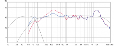
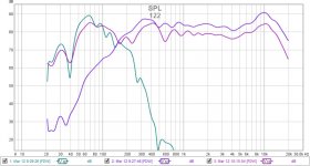
Is it a Jordan Eikona ? because in below plot took their published website response (blue trace) and overlaid with target curves (grey traces) for a 20Hz-20kHz system response with harsh XO point at 80Hz, when then i use free Edge to simulate baffle step and diffraction for OB and extract it (red trace) from published response it shows we can't reach a 80Hz BS2 roll off slope for OB, that said for info when simulated in 3,7 liters sealed it reach a BW2 86Hz slope that should be possible EQ to BS2.
Attachments
Last edited:
I have done some testing, and it seems I have finally got the grip on it!?
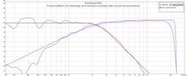
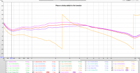
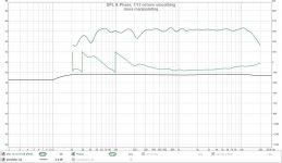
Crossovers are made in Rephase. Crossoverpoint is 2400 Hz. In theory the delay that needs to be added to the treble:
(1/2400)*0.5*1000 = 0.2083ms
Measurements are taken 80 cm from the speaker. All of them are smoothed with frequency dependent window =12.
Before I imported impulses responses from REW to Rephase I made sure to align them to zero via estimate IR in REW - Align the midrange a little bit manually. Thank you BRYTT for that advice !
I maybe could have made the acoustic responses of tweeter and midrange closer to the textbook ones, but I guess it is pretty close.
I just found that in Rephase, in the Paragraphic Gain EQ, there is an option to use so called "monotonic 12dB/oct high or low-shelf filters. This makes the EQ'ing much more easy than simple notches. Cascading two 12 dB filters is equal to 24 dB.
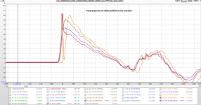
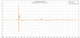
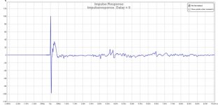
I think that the stepresponses look pretty sweet, right?
Crossovers are made in Rephase. Crossoverpoint is 2400 Hz. In theory the delay that needs to be added to the treble:
(1/2400)*0.5*1000 = 0.2083ms
Measurements are taken 80 cm from the speaker. All of them are smoothed with frequency dependent window =12.
Before I imported impulses responses from REW to Rephase I made sure to align them to zero via estimate IR in REW - Align the midrange a little bit manually. Thank you BRYTT for that advice !
I maybe could have made the acoustic responses of tweeter and midrange closer to the textbook ones, but I guess it is pretty close.
I just found that in Rephase, in the Paragraphic Gain EQ, there is an option to use so called "monotonic 12dB/oct high or low-shelf filters. This makes the EQ'ing much more easy than simple notches. Cascading two 12 dB filters is equal to 24 dB.
I think that the stepresponses look pretty sweet, right?
Attachments
Last edited:
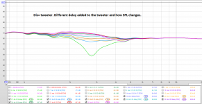
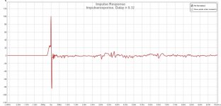
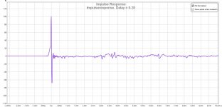
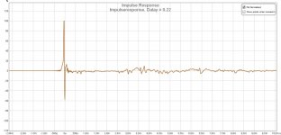
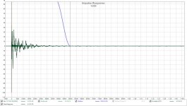
Here are the impulse responses.
Attachments
...I think that the stepresponses look pretty sweet, right?
") Looks perfect and so far delays somewhere inside area 0,28-0,32mS looks most textbook like.
Looks perfect and so far delays somewhere inside area 0,28-0,32mS looks most textbook like.A note for final delay numbers is if you refines any small bits per pass band down the road makes changes to delay so when you satisfied and lock pass band responses then any house curve tonality had to be a global speaker system correction.
Thanks sharing, will we see your new bookshelf build with Harsch filter also somewhere down the road : )
Last edited:
...A note for final delay numbers is if you refines any small bits per pass band down the road makes changes to delay so when you satisfied and lock pass band responses then any house curve tonality had to be a global speaker system correction...
Or if a global system EQ is not available then set any tweaking numbers for house curve into all summed pass bands also no matter their stop bands are really far away, it will help delay settings also stays the same.
Thanks for the tip. I use Jriver => MiniDSP DA8 => Amplifiers. So will tweak the final house-curve inserting EQ in the Jriver DSP-centre. Or maybe as an convolution with Rephase. I guess it is best to use linear-phase here or?
I must say that I have learned A LOT about active crossovers lately. This "bit" about using the Harsch method and also aligning impulse responses have taken the fidelity of my system to a WHOLE NEW LEVEL - Though impressions change over time, I will say that the current state of my system is close and in some cases better than even expensive commercial systems.
Transients are VERY fast but the overall sound is Analog/natural. This I was always missing before. So to those who have not got it right just yet - Dont give up
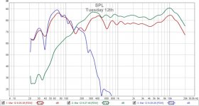
I have at the moment quit the SB65 with horn system. Think something is not just right about the sound.
The above measurement is SB17 MFC and the Alu-dome tweeter. Basreflex 16 liter, tuned to around 31-31 (with a mulitimeter and a resistor). The idea is to make a fusion with these drivers and two of the "cheap" SB20PFCC30 drivers. I got an old Dali 7A cabinet for free which I will use for that. Both midrange and bass will be aperiodic.
I must say that I have learned A LOT about active crossovers lately. This "bit" about using the Harsch method and also aligning impulse responses have taken the fidelity of my system to a WHOLE NEW LEVEL - Though impressions change over time, I will say that the current state of my system is close and in some cases better than even expensive commercial systems.
Transients are VERY fast but the overall sound is Analog/natural. This I was always missing before. So to those who have not got it right just yet - Dont give up
I have at the moment quit the SB65 with horn system. Think something is not just right about the sound.
The above measurement is SB17 MFC and the Alu-dome tweeter. Basreflex 16 liter, tuned to around 31-31 (with a mulitimeter and a resistor). The idea is to make a fusion with these drivers and two of the "cheap" SB20PFCC30 drivers. I got an old Dali 7A cabinet for free which I will use for that. Both midrange and bass will be aperiodic.
Just a tip, while getting crossovers dailed in at close distance is allright, setting up a room curve is best done at the listening spot. You can use PEQ for that within JRiver. If the room is lively a better result can be had by using averages around the listening spot for that room curve.
Tonal balance works best when used on longer time windows and you can use smoothing to get the shape close to the desired room curve.
Tonal balance works best when used on longer time windows and you can use smoothing to get the shape close to the desired room curve.
I see no way to contact Nelson on this forum.
My email is at the bottom of the opening page at FIRST WATT
and about a thousand other places.
Wesayso: Thanks for the tip. I have found this thread that explains it very well how use the spatial measurement method. Altso the "VAR" smoothing is something I will try experimenting.
A guide how to do room correction and use it in Roon - Roon Software - Roon Labs Community
But of course not before the actual crossovers are spot on.
mkane77g: Im sure you will get there soon!
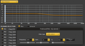
I do not have experience with a system like yours. But I have thought about that "Baffelstep" is something that probably will mask what your are measuring and what your are hearing.
Basically baffelstep is at what frequency (dependent on the baffel width) the sound will radiate. At higher freqency the sound will radiate forward. At lover frequency it will radiate both more around the speaker- in all directions. At good formula to know where baffelstep occur is 115/(width of baffle in meters). For instance a baffel width of 20 cm, the baffelstep will ocur at = 115/0.23)= 575 Hz. At this point there will be a ca -3 dB loss of low frequency compared to the higher one. Imagine a steady downgoing curve.
If you measure very close to the driver (say 5 cm) you cannot observe it. But if you measure at a longer distance (I have heard a good advice is at least 2.5 times the with of the baffel or longer) you can see it on a graph.
The maximum baffelstep-loss is -6 dB - And is room/position dependent
To address and cope with the baffelstep I normally use an "High Shelf" filter with a Q between 0.5 to 0.6 and minus 4 to 6 dB
Compensating for baffelstep is basically a matter of EQ'ing the response of the bassdriver to a straight line.
Hope it makes sense. And if you knew it already, maybe someone else can make a use of it
A guide how to do room correction and use it in Roon - Roon Software - Roon Labs Community
But of course not before the actual crossovers are spot on.
mkane77g: Im sure you will get there soon!
I do not have experience with a system like yours. But I have thought about that "Baffelstep" is something that probably will mask what your are measuring and what your are hearing.
Basically baffelstep is at what frequency (dependent on the baffel width) the sound will radiate. At higher freqency the sound will radiate forward. At lover frequency it will radiate both more around the speaker- in all directions. At good formula to know where baffelstep occur is 115/(width of baffle in meters). For instance a baffel width of 20 cm, the baffelstep will ocur at = 115/0.23)= 575 Hz. At this point there will be a ca -3 dB loss of low frequency compared to the higher one. Imagine a steady downgoing curve.
If you measure very close to the driver (say 5 cm) you cannot observe it. But if you measure at a longer distance (I have heard a good advice is at least 2.5 times the with of the baffel or longer) you can see it on a graph.
The maximum baffelstep-loss is -6 dB - And is room/position dependent
To address and cope with the baffelstep I normally use an "High Shelf" filter with a Q between 0.5 to 0.6 and minus 4 to 6 dB
Compensating for baffelstep is basically a matter of EQ'ing the response of the bassdriver to a straight line.
Hope it makes sense. And if you knew it already, maybe someone else can make a use of it
Attachments
got that, thanksMy email is at the bottom of the opening page at FIRST WATT
and about a thousand other places.
Thanks for the tip. I use Jriver => MiniDSP DA8 => Amplifiers. So will tweak the final house-curve inserting EQ in the Jriver DSP-centre. Or maybe as an convolution with Rephase. I guess it is best to use linear-phase here or?...
Nice chain there you will have wide possibilities of control, at first use always minimum phase (IIR) if you ask me because that's what we listen to and in phase follow amplitude in that domain we repair the other automatically, to correct IIR domain it will need good measurements and to look for interference after IR is aligned use "Generate minimum phase" button in REW and if that looks follow absolute measured phase there is not any reflections or interference and IIR corrections should work perfect, should there be some areas where those two phase traces don't line up (excess phase) be care full to correct in those areas and its probably best to check why and maybe try other measurements or window filters.
Where to use linear phase is to avoid excess phase from XO points so use linear phase correction and also some room reflections can work if fault is over a wider area, wesayso have also with success used linear phase for some special mid-side encode/decode filtering, that said its free to make any experiments and see what happens.
Last edited:
Thanks ! Im very happy with my chain. Really like the possibilities of DA8. Did not thought that the tabs of 1024 per channel would be enough. But so far it is. Before I used an Esi Gigaport HD+ - I would say that this is also a nice soundcard. And it was stable. I have tried other sound-cards, but I have had issues with noise and drop-outs - Even though I think my computer was/is tuned very much to audio. With the miniDSP there are no issues doing other things than audio on it. Do you use a USB-soundcard or?
Very good advices!
I can clearly see, if I measure to far away from the speaker, that phase is messed up. The FRD window = 15 normally fix that issue.
I know measuring is a huge topic - But when you start with making the impulse responses for the filter - Do you then place the microphone at a fixed position - And then take measurement of all of the drivers from this position - ie. bass, midrange and tweeter.
I see several other variants of this. One can position the mic between tweeter and mid. At tweeter height. Or very close to each of the drivers.
- Home
- Loudspeakers
- Multi-Way
- S. Harsch XO