Excel models for L3-3 test cards
Hi,
I've made for my personal training an Excel model of the L3-3 universal test card. It can be used for those who want to practice and to understand the programming of this unit, in order to measure another tubes.
I am attaching to this message a ZIP arhive that contains the folowing two files (that are also mirrored on my site, see the links):
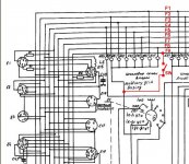
The hardware lines {A to I} on the L3-3 tester schematic diagram (and universal test card) are labeled as {F1 to F9} in the Robert W. Berger docs.
Hope that these will help .
Best regards,
Cezar
Hi,
I've made for my personal training an Excel model of the L3-3 universal test card. It can be used for those who want to practice and to understand the programming of this unit, in order to measure another tubes.
An externally hosted image should be here but it was not working when we last tested it.
I am attaching to this message a ZIP arhive that contains the folowing two files (that are also mirrored on my site, see the links):
- the Excel L3-3 universal test card;
- an Excel model for EF80, built after the Robert W. Berger docs .
The hardware lines {A to I} on the L3-3 tester schematic diagram (and universal test card) are labeled as {F1 to F9} in the Robert W. Berger docs.
Hope that these will help .
Best regards,
Cezar
Attachments
Measuring non-russian 9pin tubes with L3-3 (part1)
Good afternoon my friends,
(because here the time is 4:10PM, hi)
It's Sunday and after a couple of hours of tests and measurements, that LED from my head began to shine")
Well, for using the socket no.11 at full capacity, I just installed a switch that connects line F9 (or 'I' in the russian schematic) with the G2 power supply (the common point of the contacts {61,62,63,64,65,66}/I and 61/II.
When I want to connect F9 to the Ug2, I just push that button
Here is the modified zone (see also the attachments):
After that, I've built right from the scratch two new test-cards for EF80 and EF89. Below you may see the snapshots of these cards, and you also may download them from the ZIP file attached (or by accessing the links from my site).
NOTE (ERRATA):
In the previous post, I've labeled as "Ig2 scale" (wrong!) the test-card area for {Ua scale} - that is containing pins no. {8,9 and 10}/II . Now I've corrected that mistake. Please excuse me!
External resource links:
WARNING! VERY IMPORTANT!
When using the installed switch "ON" (i.e. line F9 connected to Ug2 power supply),
ALWAYS CHECK THAT {43/II ; 51/II; or 50/I} pins to be NOT CONNECTED !!!
Results
EF89 TEST1
Va=250V, Vg2=130V, Vg1=-2V, Vg3=0V
---> Ia = 13.8mA, Ig2 = 5.5mA and S=4mA/V
[right as in the datasheet graphics!]
EF89 TEST2
Va=250V, Vg2=100V, Vg1=-2V, Vg3=0V
---> Ia = 8.4mA, Ig2 = 3.2mA and S=3mA/V
[again, the results match the datasheet specs!]
For those that are interested, here are the links with my Excel test-cards.
Good luck and all the best !
Cezar
Good afternoon my friends,
(because here the time is 4:10PM, hi)
It's Sunday and after a couple of hours of tests and measurements, that LED from my head began to shine
Well, for using the socket no.11 at full capacity, I just installed a switch that connects line F9 (or 'I' in the russian schematic) with the G2 power supply (the common point of the contacts {61,62,63,64,65,66}/I and 61/II.
When I want to connect F9 to the Ug2, I just push that button
Here is the modified zone (see also the attachments):
An externally hosted image should be here but it was not working when we last tested it.
After that, I've built right from the scratch two new test-cards for EF80 and EF89. Below you may see the snapshots of these cards, and you also may download them from the ZIP file attached (or by accessing the links from my site).
An externally hosted image should be here but it was not working when we last tested it.
An externally hosted image should be here but it was not working when we last tested it.
NOTE (ERRATA):
In the previous post, I've labeled as "Ig2 scale" (wrong!) the test-card area for {Ua scale} - that is containing pins no. {8,9 and 10}/II . Now I've corrected that mistake. Please excuse me!
External resource links:
- EF80 test card (Excel format), last check 17Oct2010
- EF89 test card (Excel format), last check 17Oct2010
WARNING! VERY IMPORTANT!
When using the installed switch "ON" (i.e. line F9 connected to Ug2 power supply),
ALWAYS CHECK THAT {43/II ; 51/II; or 50/I} pins to be NOT CONNECTED !!!
Results
EF89 TEST1
Va=250V, Vg2=130V, Vg1=-2V, Vg3=0V
---> Ia = 13.8mA, Ig2 = 5.5mA and S=4mA/V
[right as in the datasheet graphics!]
EF89 TEST2
Va=250V, Vg2=100V, Vg1=-2V, Vg3=0V
---> Ia = 8.4mA, Ig2 = 3.2mA and S=3mA/V
[again, the results match the datasheet specs!]
For those that are interested, here are the links with my Excel test-cards.
Good luck and all the best !
Cezar
Attachments
For anyone who interested - I wrote user manual for this tester (in English), with some translations between Russian/English. Draft version is available here:
L1-3/L3-3 Vacuum Tube/Valve Tester User Manual | MacGuru HQ
If someone will find typos/mistakes, or just have a suggestion(s), please do not hesitate to e-mail me.
L1-3/L3-3 Vacuum Tube/Valve Tester User Manual | MacGuru HQ
If someone will find typos/mistakes, or just have a suggestion(s), please do not hesitate to e-mail me.
How to make new L3-3 testcards
Hi all,
Because the german SPlan software (used by A.Rudolph to make extra testcards sets) is not free, I developed another practical method, using ExpressPCB software that you can download and use for free.
Here is a snapshot of the L3-3 universal card (translated in English) made with ExpressPCB:
The testcard file is attached to this message, but you can also download from my page.
For those who are interested to see the EF89 testcard made with ExpressPCB, here is a snapshot:
Tomorrow I'll be back to put here also the download link.
WARNING! These testcards are designed to use the F9 (I) line linked to Ug2, trough an extra switch. See my previous postings for details.
Best regards,
Cezar
Hi all,
Because the german SPlan software (used by A.Rudolph to make extra testcards sets) is not free, I developed another practical method, using ExpressPCB software that you can download and use for free.
Here is a snapshot of the L3-3 universal card (translated in English) made with ExpressPCB:
An externally hosted image should be here but it was not working when we last tested it.
The testcard file is attached to this message, but you can also download from my page.
For those who are interested to see the EF89 testcard made with ExpressPCB, here is a snapshot:
An externally hosted image should be here but it was not working when we last tested it.
Tomorrow I'll be back to put here also the download link.
WARNING! These testcards are designed to use the F9 (I) line linked to Ug2, trough an extra switch. See my previous postings for details.
Best regards,
Cezar
Attachments
Last edited:
EF89 final testcard & measurements
Hi all,
Sorry for the delay. I'm back to put here the final form of the EF89 testcard made with ExpressPCB (revision 1.1 from 23.10.2010) and also the results of some measurements for its transconductance (slope).
You will see here two screenshots. All of the files for EF89 are archived and attached in a ZIP file that you may also download from my site.
This is the snapshot of the final form of the EF89 testcard. Please note that it is using socket no.11 and the 9th line is connected to the Ug2 power supply via a small switch (see my previous posts about this). This card is usable ONLY in this form of hardware setup !
... and here is a snapshot of the slope compared measurements:
3 sets of direct measurements with L3-3 are in the TABLE1, for Ug1 = -1, -2 and -3V. I kept Ua=250V, Ug2=100V and Ug3=0 unchanged (constant).
As you can see, in TABLE2 I've applied the classic formula of transconductance, and the results are very close to the readings from the L3-3 slope dynamic tests.
Here you cand download the:
... and here is the ZIP file with all of docs included .
If anyone want to write me any direct mail, please do this to the
following E-mail address: yo3fhm [at] yahoo [dot] com .
Best of luck,
Cezar
Hi all,
Sorry for the delay. I'm back to put here the final form of the EF89 testcard made with ExpressPCB (revision 1.1 from 23.10.2010) and also the results of some measurements for its transconductance (slope).
You will see here two screenshots. All of the files for EF89 are archived and attached in a ZIP file that you may also download from my site.
This is the snapshot of the final form of the EF89 testcard. Please note that it is using socket no.11 and the 9th line is connected to the Ug2 power supply via a small switch (see my previous posts about this). This card is usable ONLY in this form of hardware setup !
An externally hosted image should be here but it was not working when we last tested it.
... and here is a snapshot of the slope compared measurements:
An externally hosted image should be here but it was not working when we last tested it.
3 sets of direct measurements with L3-3 are in the TABLE1, for Ug1 = -1, -2 and -3V. I kept Ua=250V, Ug2=100V and Ug3=0 unchanged (constant).
As you can see, in TABLE2 I've applied the classic formula of transconductance, and the results are very close to the readings from the L3-3 slope dynamic tests.
Here you cand download the:
... and here is the ZIP file with all of docs included .
If anyone want to write me any direct mail, please do this to the
following E-mail address: yo3fhm [at] yahoo [dot] com .
Best of luck,
Cezar
Attachments
L1-3: EF89 Card from Arthur Rudolph -Danger?
Hello, Mr. yo3fhm
if you test an EF89 with my card without adapter box, you will destroy the tester!
If you look on my card, you will read "socket A5", this means socket Nr.5 on the adapter box.
Many noval tubes need an other wiring than on the Nr.11 and Nr.12 on the tester, thus i designed and build an adapterbox, see
L1-3 Adapterbox
If you need more information pleas write me.
All my cards where socket begins with "A" need the adapter.
Yours sincerely
arthur
Hi everyone, I just happened to catch a L3-3 out of a pile of junk. The condition of this one was very very bad: no tube, no lid cover, no card, miss something here something there inside, the meter is broken ... but after some study I think I can repair this one.
Now I'm trying to rewire some broken connections and replace the bad components, and the first thing I do is recap, what I want to ask is should I use new electrolytic ones with high value than the original, or should I use the same?
Regards,
Duong.
... but after some study I think I can repair this one.Now I'm trying to rewire some broken connections and replace the bad components, and the first thing I do is recap, what I want to ask is should I use new electrolytic ones with high value than the original, or should I use the same?
Regards,
Duong.
L3-3 Recap and restauration
Hello Mr. Duong,
you should use the same values of capacity like original, because this could affect the stabilisators and the measuring of mutual conductance.
If you can find MP condensors which fit- no problem.
Electrolytic condensors should withstand high temperatures, use mi. 105°C types, because the tester goes hot in use.
If you need the original cards as pdf you can downlowd them from
http://www.afrudolph.de/l1-3/l33.zip.
Good luck for restauration.
Regards
arthur
(Dumb) question
Hello, I have a question, probably a dumb one. I'd like to change the cord of my L3-3, using a 3-wires new cord and plug.
Can I connect the yellow-green earth wire to the earth pin on the front of the tester? I guess this would ensure a safer electrical connection, right?
Or am I completely wrong?
Thanks for your help.
Steve
Hi all,
I have an L3-3 which I am trying to resurrect, but am no electronics wizard so would appreciate any help you can offer! I am following the Klemkosky translations, all is well until 'calibration of the transconductance tester'.
I put Parametri switch to Position 'S', rocker switch 'S' to 'Calibr', push button to 'Measure' and nothing happens. The meter stays around zero. I can adjust the pot just fine, and it makes a minuscule difference to the zero point. What has happened, and what can I do about this? Is there a further pot inside the chassis of the tester I can adjust to help this or what do you think has happened?
many thanks in advance!
Perhaps I should add that at the stage when I put the tube tester card (I chose 6p14p tube p-6 card), and add all the pins (but no tube) the meter moves to 72 on the scale - seemingly from the pins inserted into positions 66,69,70,72. I don't know what all this means but hope it helps.
Also I can't set the MKA calibration to 120 either. The zero point sets fine, but there is nothing showing on the higher calibration point except the same kind of tiny deflection as when setting the 'S' transconductance.
Any ideas?
Also I can't set the MKA calibration to 120 either. The zero point sets fine, but there is nothing showing on the higher calibration point except the same kind of tiny deflection as when setting the 'S' transconductance.
Any ideas?
This should work fine (works for me) with the 6A7 or 6K3 cards. Put all pins for the card in, not only the ones you think you found that matter. All this circuitry is on the left side of my tube tester.I put Parametri switch to Position 'S', rocker switch 'S' to 'Calibr', push button to 'Measure' and nothing happens.
http://www.diyaudio.com/forums/tubes-valves/107221-russian-l3-3-tube-tester-9.html
۞۞ Tube tester collection
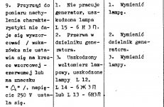
From user manual in Polish:
"9. If slope meter can not be calibrated and voltage is properly calibrated (250V)
1. Generator is not working : replace VL15 (6N3P)
2. A break in the resistor voltage divider chain : replace divider
3. Valve voltmeter is out of order: replace VL12 (6J3P), VL14 (6J3P) or VL13 (6N3P)"
۞۞ Tube tester collection
From user manual in Polish:
"9. If slope meter can not be calibrated and voltage is properly calibrated (250V)
1. Generator is not working : replace VL15 (6N3P)
2. A break in the resistor voltage divider chain : replace divider
3. Valve voltmeter is out of order: replace VL12 (6J3P), VL14 (6J3P) or VL13 (6N3P)"
Attachments
HI all,
thanks for the replies, and the kind offer of help from Klemkosky. I'd kind of given up but will now address the points in Zibi's post and post such results as I can get. I now have a rather old oscilloscope which should help a bit. Re your post kw71, I think I did put all the pins in, just not the tube. I was just pointing out which ones seemed to make the meter move (in case it helped!) but it seems to have confused the matter, sorry.
thanks for the replies, and the kind offer of help from Klemkosky. I'd kind of given up but will now address the points in Zibi's post and post such results as I can get. I now have a rather old oscilloscope which should help a bit. Re your post kw71, I think I did put all the pins in, just not the tube. I was just pointing out which ones seemed to make the meter move (in case it helped!) but it seems to have confused the matter, sorry.
Anyone still interested in this thread?
I've just come across another bunch of L1-3s, L3-3s and thier Chinese brothers (about 30 pieces), there was even one L1-3 with all function descriptions written in German! Some of the testers are still in good shape though the top lid, the cards and spare part are all gone.
Could not resist the temptation, I take home 2 L3-3s with a good price and with the hope to resurrect those beasts
Luckily my attemp to restore the first one was succeed. With my experiences, I decided to replace all capacitors, except the PIO and silver mica one, along with the leaky semiconductor diodes. It took some times to do this job, then the tester can be plugged in and warmed up for the first time in 20 years (the latest calibrated date on the tester was in 2002).
Then there came calibration stage, it took me quite sometime again to check and replace some parts involved in meter circuits. Again it was very lucky that most of the wire wound resistors are still good, but the ones that help to correct the meter display range (R92, R100, R101 in schematic and part list) need to be checked and adjusted carefully, as well as the R85 which involves in mains (127/220VAC) calibration circuit. I also realized that there were many variations of this L3-3, because many devices in my L3-3 were mark with different numbers than in schematic and manual, I had to compare between 2 russian versions and one german versions of the operation manual to trace out things.
After this difficult step, I just needed to follow others calibration steps as in the manual, and now the tester can work fine with minor errors
L3-3 and L1-3
Hi hoangduongo,
very interesting information. The foremer east-german peopl army had L1-3 an L3-3 with german manual for their russian equipment, there were also testers with front plate writing in german language.
Thats right, there were some variations of L1-3 and L3-3 depending of the year of manufactoring and the plant. There were two plants that made this testers: Kalibr in Minsk (Belarus) and SPB-pribori in St. Petersburg (former Leningrad).
I use an very old L1-3 from 1964 and I'm very happy with it.
- Home
- Design & Build
- Equipment & Tools
- Russian L3-3 tube tester