Pass DIY Addict
Joined 2000
Paid Member
Glad you got something out of it. Many thanks go to Gabevee as well for the inspiring design. The cheapest place I have found so far for hammond transformers is Angela. They're in Maryland as well. For power I used the 272JX. It has ample current for this project (246ma). Mine gets warm after 6 or so hours but I can still touch it. AES is pretty good for resistors and incidentals. Check you resistors voltage rating carefully. There are some out there that are rated lower than 300 volts. Good luck and enjoy.")
Unbelievable
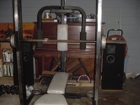
Well, I changed the cathode resistor back to 360 ohms. Then I emptied the wall out where my rig sits and WOW. In the pic the piano is gone and the bookcases to the left are gone. The only thing on that wall now is my stereo. I moved my TLs back to around 8"s off the wall and opened them up to around 10 to 12 feet. I can't describe the difference. All that other stuff was not allowing the speakers to acoustically couple the stereo field. Not so any more. It would seem this amp will turn out to be a bargain if you have transmission line speakers. The bass is excellent out of mine. A couple more watts and it would be thumping me in the chest at 10 feet, really , it's that good. My speakers are the DCM Time Frame series, TF600. I have a set of 350s that need work. I cut the old coverings off these and recovered them with 1/4" black heavy felt. I also removed the felt pad from behind the top grill and like the mids more without it. The port is rear firing and each one has two rear firing tweeters, one on each side at a 45 deg. shot off axis. It seems like my stereo just comes out of the wall and it just disproves the theory that you get what you pay for, I got more.
Well, I changed the cathode resistor back to 360 ohms. Then I emptied the wall out where my rig sits and WOW. In the pic the piano is gone and the bookcases to the left are gone. The only thing on that wall now is my stereo. I moved my TLs back to around 8"s off the wall and opened them up to around 10 to 12 feet. I can't describe the difference. All that other stuff was not allowing the speakers to acoustically couple the stereo field. Not so any more. It would seem this amp will turn out to be a bargain if you have transmission line speakers. The bass is excellent out of mine. A couple more watts and it would be thumping me in the chest at 10 feet, really , it's that good. My speakers are the DCM Time Frame series, TF600. I have a set of 350s that need work. I cut the old coverings off these and recovered them with 1/4" black heavy felt. I also removed the felt pad from behind the top grill and like the mids more without it. The port is rear firing and each one has two rear firing tweeters, one on each side at a 45 deg. shot off axis. It seems like my stereo just comes out of the wall and it just disproves the theory that you get what you pay for, I got more.
Attachments
Pass DIY Addict
Joined 2000
Paid Member
Hi Eric,
Of course, I am being facetious. He is using the Hammond 125SE. It has a limited frequency response. But they do sound nice. I am talking about any transformer that will produce 20-20kHz within reasonable distortion and range specs (+/- XdB).
Hammond's 16XX Single Ended series is very good sounding. I am sure Lundahl will be superior, but then there goes the budget aspect. I recommend One Electron over both, because they are $89 each and just right as far as power handling, and sound much better than the Hammonds.
Yes, I am talking about output transformers.
Gabe
Pass DIY Addict
Joined 2000
Paid Member
Hi Gabe,
Thanks for your reply! Yes, one of the attractive aspects of your design is the budget price - a nice place to start! At the same time, I wouldn't mind spending a little bit more money to build a better amp. I'm not really interested in >$600 for a set of Tangos, but $90 isn't bad...
I assume that this one from One-Electron would be a suitable replacement?
http://www.one-electron.com/Trans/UBT3_10.pdf
Eric
Going back to the original 2A3 project again :
Do you need the 193S choke specifically? I see the schematic states 1-5 henry choke, ...
193S = 1H, 1000ma, 5.75 ohms, 1000VDC Do we really need the ratings to be this high? The reason i ask is cost-based....the 193S is $70
Is there a cheaper 193 version that could get the job done ?
-Maz
Do you need the 193S choke specifically? I see the schematic states 1-5 henry choke, ...
193S = 1H, 1000ma, 5.75 ohms, 1000VDC Do we really need the ratings to be this high? The reason i ask is cost-based....the 193S is $70
Is there a cheaper 193 version that could get the job done ?
-Maz
Correction!
It is the 156R, and they are currently on sale for $8.50. I am pissed because I recently bought a few at their regular price .
.
No big deal. I will just get a few more.
At any rate, I thought I said 1-5 H. I could be mistaken. Need to go back to the page...
So Skippy, what are your dimensions? I see from your latest picture that you lift.
Can't say I am an Adonis or anything, but I bulge here and there. Mostly in the midsection, tho. Comes from happy living and a great cook for a wife. She can take the simplest meals and make them gourmet.
At any rate, the guns are 19 inches (I know, everybody raves about my guns. Can't stand them tho. Don't do much and they grow 20%!!! Wish the chest was bigger!), chest about 50, legs not to shabby, but the gut offsets much of it. There is a real big and tight sixpack under the layer, tho. I do crunches with the pulley machine at the gym. Can bench 330 on a bad day. Squat about 1400 pounds. My legs are incredibly powerful (runs in the family... no pun intended!), and yet the least worked out... until recently (hence why my weight has gone up!). I weigh about 220, but if I lost the gut can be a lean 195. That at 5'6". Man that muckle weighs alot!
Later!
Gabe
It is the 156R, and they are currently on sale for $8.50. I am pissed because I recently bought a few at their regular price
.No big deal. I will just get a few more.
At any rate, I thought I said 1-5 H. I could be mistaken. Need to go back to the page...
So Skippy, what are your dimensions? I see from your latest picture that you lift.
Can't say I am an Adonis or anything, but I bulge here and there. Mostly in the midsection, tho.
Comes from happy living and a great cook for a wife. She can take the simplest meals and make them gourmet.At any rate, the guns are 19 inches (I know, everybody raves about my guns. Can't stand them tho. Don't do much and they grow 20%!!! Wish the chest was bigger!), chest about 50, legs not to shabby, but the gut offsets much of it. There is a real big and tight sixpack under the layer, tho. I do crunches with the pulley machine at the gym. Can bench 330 on a bad day. Squat about 1400 pounds. My legs are incredibly powerful (runs in the family... no pun intended!
), and yet the least worked out... until recently (hence why my weight has gone up!). I weigh about 220, but if I lost the gut can be a lean 195. That at 5'6". Man that muckle weighs alot!Later!
Gabe
No, I went back and checked. You said 1-5H, and I went with 4. I just screwed up when I listed a 193S. Where do you get your stuff? Angela is closed until the end of the month.
As for lifting, I started that back in september when I quit smoking. I didn't want to gain the weight. I also ride about 5 to 10 miles a day on the bike. It's not really to get big just to stay in shape. I'm 5'10" and 190 lbs. The most important part of the whole thing is eating right and that's the hardest thing to get right with
Now, if your squating 1400 lbs you look more like arnold than me.
As for lifting, I started that back in september when I quit smoking. I didn't want to gain the weight. I also ride about 5 to 10 miles a day on the bike. It's not really to get big just to stay in shape. I'm 5'10" and 190 lbs. The most important part of the whole thing is eating right and that's the hardest thing to get right with
Now, if your squating 1400 lbs you look more like arnold than me.Pass DIY Addict
Joined 2000
Paid Member
Add PS switches?
Hi Gabe and PF: Comparing the power supply of Gabe's 2A3 to other designs I've come across, might a valuable addition include one more power supply switch? Keep the original switch to the primary of the power supply transformer, but add another switch on the B+ line. This way you could allow the tubes to heat up a little before applying the higher voltage to them.
Or is there some aspect of this deign/tube combination that makes this addition unncessary?
Thanks!
I've asked this question before too, Eric, and the response i got was that a standby switch is sort of a guitar-amp thing...and that stereo amps don't really need it. Some will argue that tube life will be extended with it...but i've got plenty of amps from the 30's-50's with the original tubes in them and no standby switch.
Some rectifier tubes like the GZ34 have a slow start feature to them....that gives the heaters time to do their thing before high B+ is applied.
I have a limited understanding of it, but this is what i have gathered.
Correct me if i am wrong, guys.
-Maz
Some rectifier tubes like the GZ34 have a slow start feature to them....that gives the heaters time to do their thing before high B+ is applied.
I have a limited understanding of it, but this is what i have gathered.
Correct me if i am wrong, guys.
-Maz
Be kind to the audio valves
If you use a pair of efficiency diodes (damper diodes in US parlance), such as 6DN3, the warm-up will definitely be sufficiently slow that the output valves will be nicely warm before the HT arrives. Other possibilities are:
Contacts of thermal delay relay in series with rectifier heater supply.
Separate mains transformer for HT, switched by thermal delay relay.
Magnetmaz and others,
The purpose for the stand by switch in this case would be for the fact that in that circuit the B+ is derived with solid state rectifiers. So there wil be a full B+ at the plates of the tubes. This causes a phenomenon called cathode stripping.
Now, whether this is a major concern or not is in my opinion a matter of... opinion. While the phenomenon is a fact, the concern may be blown out of proportion. After all, the original tubes were straight DC from batteries. My battery radios actually have the full DC on the plates at all times, and merely turn on the filament supply!
So.. what's up with that!?
Well, some of my radios came with original tubes and needless to say they still work.
Now, with AC powered units, the solid state rectifier will cause the B+ to start at a much higher voltage than at idle, which still makes the switch a moot point, because without a load the tubes will see the full B+ effect with tube rectifiers as well as solid state.
I don't know... which is worse, applying a high voltage to a cold cathode that is not ionized, or to a cathode that is ionized with heat and already giving off electrons? I would think the draw would be greater with the cathodes hot, not to mention how loose the boron (or whatever the material is on the cathode) atoms/molecules will be with the heat as opposed to cold.
Anyone for a new debate?
Gabe
CATHODE STRIPTEASE.
Hi Gabe,
We discussed this topic already but here's some interesting read:
A DEEPER LOOK AT THE PHENOMENON OF CATHODE STRIPPING IN THERMIONIC VALVES -------------------------------------------------------------------------
From a rec.audio.tubes article posted Dec.'96 By: J.H. van de Weijer
One may assume that a thermionic valve's susceptibility to the stripping phenomenon primarily depends on its cathode's design, and indeed that the side effects caused by this are most prone to be seen in high grid impedance low level signal tube circuits and their aging behavior:
Indirectly heated (generally Nickel) cathodes coated with a rare earth metal oxide electron emission "cement" compound are prone to mechanical stress caused by thermal cycling; i.e.: the heating and cooling of the cathode. (Manufacture dependent).
The ceramic nature of the indirectly heated cathode's emissive coating with its (from the metal cathode carrier) differing thermal expansion coefficient may cause surface material to crack and become "loose". The thus gradually "powdered" ceramic cathode emission surface may keep minute amounts of electrical charge stored after cooling down; the surface in cold state remains nonconductive. Minute amounts of these cathode borne particles, either with remaining charge or electrically polarized upon sudden apply of anode voltage, may "dust off" and clog onto the most nearby "sieve" i.e.: the control grid; cathode stripping has happened, and here it is that this less heard of tube degradation/aging mechanism (not discussing others) occurs!
Consider this:
The grid clogged particles due to radiant heating from the nearby cathode will start to behave as pointwise cathodes themselves, causing beyond normal grid current, this has the effects of:
-Drift in those high impedance biased control grid circuits: And this just in the unwanted direction: Take a tube endstage which is capacitive coupled from the phase inverter and DC biased through (say) 50 kOhms: Current runs from the anode into the control grid and therefore shifts the grid bias voltage to a less negative value... There you go... (Ever wondered why some tube manufacturers specify a maximum grid bias resistance?) -Causing excess noise. -Etcetera, you don't want to know.
Now, how to be most gentle to your indirectly heated tubes and give them a long life: (and this also applies for all fellow guitar players having a "stand by" switch at hand):
SWITCH ON: Switch on from standby mode: i.e. only fire the filaments, wait somewhat longer than fully "glown" up, then switch from standby to power (B+). (i.e.: B+ may be suddenly switched on, but only after full filament warm-up) (with regards to "cathode stripping": The cathode is now conductive: All localized cathode charge will have drained).
SWITCH OFF: The same sequence reversed: I.e.: Turn off B+, wait, and only then turn off the filament supply; This will gradually and properly discharge all charges. With regards to cathode Stripping; this will assure no charge will remain stored locally on the susceptible cathode surface and so forth...
Copyright 1996 J.H. van de Weijer
This article may be freely distributed, stored, copied and printed for non- commercial use, provided the integral text including this notice is kept unmodified.
Cheers,
CATHODE MATERIALS.
Hi,
Definetely NOT boron, you probably meant barium(oxide)?.
Also used as materials are nickelalloys.
Cheers,
Hi,
not to mention how loose the boron (or whatever the material is on the cathode)
Definetely NOT boron, you probably meant barium(oxide)?.
Also used as materials are nickelalloys.
Cheers,
- Status
- This old topic is closed. If you want to reopen this topic, contact a moderator using the "Report Post" button.
- Home
- Amplifiers
- Tubes / Valves
- Running Tube Amp Construction