Moving Forward (Allways)
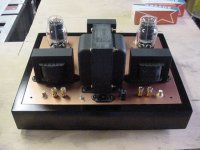
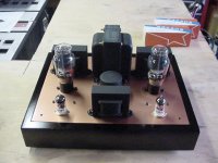
Now for the finish. Okay, I know some of you are going to cringe but, IMO the oak stock was not up to par for a natural finish (I said this was a quicky, remember) so, I have given it a black laquer finish. I use a local laquer from Ace hardware which goes on thinner than any other I've found. I would suggest trying a few different brands if you go this route and pick the thinnest one. It will go on smoother the thinner it is. I acheived this finish with multiple coats and fine sanding in between to fill the grain. If you decide to paint your finish use a grain free wood like pine or poplar. Unfortunately all I had was oak and this was a quicky. For sanding i use a 3M sanding block style sponge. You can buy them in 3 or 4 different textures and the paint doesn't get stuck to them. Once I get the grain filled and an even coat of black I fine sand it till it's as smooth as glass, without sanding through to bare, and then put one good clear gloss coat on it and, Voila' done. The final sanding takes everything down to a very even and blemish free flat and then I gloss it back and get a deep piano black finish. I have kinda used this finish style into the ground I suppose but a lot of people seem to like it as it's different. I am going to try the design with the choke where it's at and have found room under the top plate if neccesary. I should get to wiring and testing by this weekend. Cheers
Now for the finish. Okay, I know some of you are going to cringe but, IMO the oak stock was not up to par for a natural finish (I said this was a quicky, remember) so, I have given it a black laquer finish. I use a local laquer from Ace hardware which goes on thinner than any other I've found. I would suggest trying a few different brands if you go this route and pick the thinnest one. It will go on smoother the thinner it is. I acheived this finish with multiple coats and fine sanding in between to fill the grain. If you decide to paint your finish use a grain free wood like pine or poplar. Unfortunately all I had was oak and this was a quicky. For sanding i use a 3M sanding block style sponge. You can buy them in 3 or 4 different textures and the paint doesn't get stuck to them. Once I get the grain filled and an even coat of black I fine sand it till it's as smooth as glass, without sanding through to bare, and then put one good clear gloss coat on it and, Voila' done. The final sanding takes everything down to a very even and blemish free flat and then I gloss it back and get a deep piano black finish. I have kinda used this finish style into the ground I suppose but a lot of people seem to like it as it's different. I am going to try the design with the choke where it's at and have found room under the top plate if neccesary. I should get to wiring and testing by this weekend. Cheers
Attachments
Skippy,
i have to say that amp looks wonderful. im going to be building a 2A3/6A3 amp this weekend myself (after all parts arrive), and was wondering how big the holes that you made are for the 2A3's in the chassis? im going to be mounting the sockets underneath (like you), just so you know what i am dealing with.
i have to say that amp looks wonderful. im going to be building a 2A3/6A3 amp this weekend myself (after all parts arrive), and was wondering how big the holes that you made are for the 2A3's in the chassis? im going to be mounting the sockets underneath (like you), just so you know what i am dealing with.
Dmitry:
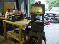
Thanks for the compliment, and good luck with your project as well. The holes i punched wound up, actual size, 1 and 3/8ths of an inch. It worked out to be the third cutter from the right in the pix that shows the greenlee knockout punch. It is the 1 inch trade size greenlee knockout punch. Notice I am using the words trade size and actual size here. For those who are not aware sometimes when you ask for a 1/2 inch hole saw you wind up with a 7/8ths inch cutter. This is because of the difference in actual size to trade size. Trade size is used to match a particular cutter to a piece of pipe. So a 1/2 inch hole saw would cut a 7/8th's hole so a 1/2 inch piece of pipe will fit through it. A 1 inch knockout punch cuts a 1 and 3/8ths hole for the outside diameter of a 1 inch pipe.
The 2A3 just fit through the hole, so I put my bolts in loose and then plugged in the tube and then tightened the bolts. If you use ceramic sockets don't torque too hard or they might crack. Good luck and let everyone know how it goes.
")
Thanks for the compliment, and good luck with your project as well. The holes i punched wound up, actual size, 1 and 3/8ths of an inch. It worked out to be the third cutter from the right in the pix that shows the greenlee knockout punch. It is the 1 inch trade size greenlee knockout punch. Notice I am using the words trade size and actual size here. For those who are not aware sometimes when you ask for a 1/2 inch hole saw you wind up with a 7/8ths inch cutter. This is because of the difference in actual size to trade size. Trade size is used to match a particular cutter to a piece of pipe. So a 1/2 inch hole saw would cut a 7/8th's hole so a 1/2 inch piece of pipe will fit through it. A 1 inch knockout punch cuts a 1 and 3/8ths hole for the outside diameter of a 1 inch pipe.
The 2A3 just fit through the hole, so I put my bolts in loose and then plugged in the tube and then tightened the bolts. If you use ceramic sockets don't torque too hard or they might crack. Good luck and let everyone know how it goes.
paulb said:Hey Skippy,
I'm not a tube fan but your amp looks magnificent. I could probably stand having one of those in my living room.
Hmmm, Grey's influence is rubbing off...
Thanks. Grey is still around? I havn't seen him post lately.
Out From Under The Rock
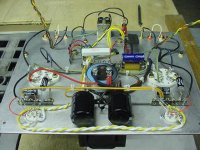
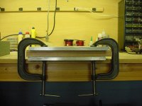
Whew, I've been on the bench wiring since 3:00 and it's now 10:56. They never look like a lot until you go to wire them up. I will include a quick peek pic for those of you who want to look but, the write up will have to wait until tommorrow. I usually walk away at this point and do something else for an hour or so and I will sleep on this before I recheck and fire it up. You'll be surprised at what you might find this way. I should have a lot of write ups tommorrow and answres for Peter on the tools I used as well.
Whew, I've been on the bench wiring since 3:00 and it's now 10:56. They never look like a lot until you go to wire them up. I will include a quick peek pic for those of you who want to look but, the write up will have to wait until tommorrow. I usually walk away at this point and do something else for an hour or so and I will sleep on this before I recheck and fire it up. You'll be surprised at what you might find this way. I should have a lot of write ups tommorrow and answres for Peter on the tools I used as well.
Attachments

With A Bang and a Flash
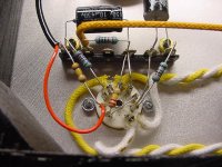
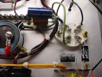
I've heard that before, somewhere (Eh Morse). Well success at last but first, lets discuss how I got there. In the pic, in the previous post, we see ordered kaos, so lets start at the beggining. First, I wire up the filaments. Just in front of the 120v filter/connector in the back we see the two yellow 5v winding leads curling up and back down to the rectifier bridge which has been bent over to 90'degrees. Coming off of the bridge is a black and red cloth covered wire going to the big 35v capacitor. From there it splits, red to one 2A3 filament and black to the other 2A3 filament. Gabe has drawn this so that positive and negative connect on opposite sides of the filaments. This assures electron flow in the same direction through each filament. I connected red to terminal 4 and black to terminal 1.
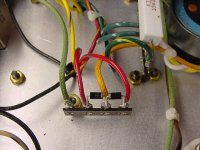
The green wire comes of the 2A3 on the right and goes down to the bias resistor and capacitor and then over to the laft 2A3. The bias resistor I used was a 25watt 300 ohm aluminim I had laying around and seems to work fine. My measured voltage on this circuit loaded was around 5.1 volts. The 6.3 volt circuit starts at the same point as the 5v yellow leads and they are the green set coming out and going to a terminal set underneath the white cement style power resistor. There I convert them to the twisted yellow and white pair that runs to the tube sockets in front for the 12AX7's. These are kept as far away as possible from everything else as they are AC and can cause hum.
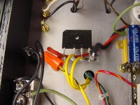
The 12AX7 has a dual filament and can be hooked up either 12v or 6.3v. The main B+ comes out on the two red wires just to the left of the big white power resistor and connect to the terminals where my diodes are located. After going through the diodes one orange colored wire comes off and up front to the terminal set with the two black capacitors. the choke leads can be seen coming through the top plate between these capacitors and the orange wire comes into one side of this terminal block and out the other. It them loops to each terminal block set for each 12AX7 tube. These capacitors are something I had lying around and are a little big (270mf each), but they work. The rest of the circuit is simple, see the capacitor coming off of pin 3 on the 2A3 sockets wired back to pin 8 of the 12AX7. Also off of pin 3 is a resistor to ground. I will show some other pics of these details so you can follow along with the schematic if you so choose. Perhaps the way I do things is not the best way but it is another way.
I had a problem with massive amounts of hum and really low voltage when I initially started up. My voltage was around 145 volts and the ac at the output was 145mv's (yeow). My white power resistor was too hot to touch as well so oops. I unbraided the remaining output leads and capped them off, removed one of the black B+ filter caps and clipped the yellow/black striped 5v winding center tap off of ground where I had it attached. That cured it so I re installed the filter cap and still okay. Voltages were back up, 311v on the 2A3's and 295v on the 12AX7's, and absolutely no noise or hum whatsoever. I dodged a bullet on the noise as the choke is still front and center up top Once I got all that straight I could find no more excuses to not put it in the system.
This is definately a SE amp , no doubt about that You can easily pick out the placement on everything and I had no trouble at all hearing the different instruments. The bass is excellent through my TL's. The mids are just as one would expect from a SE triode. The highs are suspect for now although I will wait until burn in on everything first as I'm using the 125ESE's. All in all, for what I have in this amp, I got a bargain the way it sounds.
I will post more pics soon as well as Peter's question.
I've heard that before, somewhere (Eh Morse). Well success at last but first, lets discuss how I got there. In the pic, in the previous post, we see ordered kaos, so lets start at the beggining. First, I wire up the filaments. Just in front of the 120v filter/connector in the back we see the two yellow 5v winding leads curling up and back down to the rectifier bridge which has been bent over to 90'degrees. Coming off of the bridge is a black and red cloth covered wire going to the big 35v capacitor. From there it splits, red to one 2A3 filament and black to the other 2A3 filament. Gabe has drawn this so that positive and negative connect on opposite sides of the filaments. This assures electron flow in the same direction through each filament. I connected red to terminal 4 and black to terminal 1.
The green wire comes of the 2A3 on the right and goes down to the bias resistor and capacitor and then over to the laft 2A3. The bias resistor I used was a 25watt 300 ohm aluminim I had laying around and seems to work fine. My measured voltage on this circuit loaded was around 5.1 volts. The 6.3 volt circuit starts at the same point as the 5v yellow leads and they are the green set coming out and going to a terminal set underneath the white cement style power resistor. There I convert them to the twisted yellow and white pair that runs to the tube sockets in front for the 12AX7's. These are kept as far away as possible from everything else as they are AC and can cause hum.
The 12AX7 has a dual filament and can be hooked up either 12v or 6.3v. The main B+ comes out on the two red wires just to the left of the big white power resistor and connect to the terminals where my diodes are located. After going through the diodes one orange colored wire comes off and up front to the terminal set with the two black capacitors. the choke leads can be seen coming through the top plate between these capacitors and the orange wire comes into one side of this terminal block and out the other. It them loops to each terminal block set for each 12AX7 tube. These capacitors are something I had lying around and are a little big (270mf each), but they work. The rest of the circuit is simple, see the capacitor coming off of pin 3 on the 2A3 sockets wired back to pin 8 of the 12AX7. Also off of pin 3 is a resistor to ground. I will show some other pics of these details so you can follow along with the schematic if you so choose. Perhaps the way I do things is not the best way but it is another way.
I had a problem with massive amounts of hum and really low voltage when I initially started up. My voltage was around 145 volts and the ac at the output was 145mv's (yeow). My white power resistor was too hot to touch as well so oops. I unbraided the remaining output leads and capped them off, removed one of the black B+ filter caps and clipped the yellow/black striped 5v winding center tap off of ground where I had it attached. That cured it so I re installed the filter cap and still okay. Voltages were back up, 311v on the 2A3's and 295v on the 12AX7's, and absolutely no noise or hum whatsoever. I dodged a bullet on the noise as the choke is still front and center up top
Once I got all that straight I could find no more excuses to not put it in the system. This is definately a SE amp , no doubt about that
You can easily pick out the placement on everything and I had no trouble at all hearing the different instruments. The bass is excellent through my TL's. The mids are just as one would expect from a SE triode. The highs are suspect for now although I will wait until burn in on everything first as I'm using the 125ESE's. All in all, for what I have in this amp, I got a bargain the way it sounds. I will post more pics soon as well as Peter's question.
analog_sa said:Hey Skippy
Do you mind telling us what wood and metal-working instruments did you use. I am beginning to contemplate the horrors of mechanical work having seen all your pretty pictures
cheers
peter
As promised a thorough response. Sorry it took so long but I am now through in the garage and all I have to do now is listen.
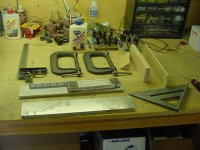
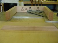
I will include a pic of the wood working tools in this post. The metal working tools consist mainly of drill bits and knockout punches. The punches I covered in a previous post, the drill bits came out of a large index. You will need, at the minimum, a drill for the metal working. I use a drill press and upright bandsaw, as well as everything else listed here. For woodworking I use a table saw for all my cuts and the assorted tools in the pic. The clamps and plate are used for gluing the wall pieces together. The large square is for gluing the corners together. It helps me hold the 90's perfect.
Bear in mind that I have a shop with a lot of tools in it. If you don't already have most of what you need it can get expensive quick if your only going to build one amp. I build a few a year, as well as other things. If your mechanically inclined and have most of the tools, I say go for it. If your not sure or want to save money, Welborne Labs sells the oak chassis with top and bottom plates already built. They even offer a punching service as well. They are not to bad with their pricing on these either. I will post a group showing how I build the chassis.
Attachments
- Status
- This old topic is closed. If you want to reopen this topic, contact a moderator using the "Report Post" button.
- Home
- Amplifiers
- Tubes / Valves
- Running Tube Amp Construction