

Hi there,
first results, though severy limited by the quality of test equipment currently available here (1ch 20MHz scope, simple signal gen, both 30+ years old).
Input signal: Square wave 1kHz, 1V/div

Output signal into 10 ohms: 10V/div
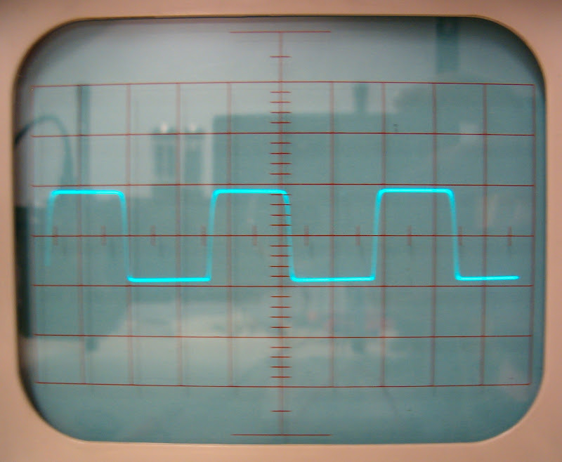
Input signal: Square wave 10kHz, 1V/div

Output signal into 10 ohms: 10V/div

Anyone able to extract some useful information from that?
Regards,
Andreas
first results, though severy limited by the quality of test equipment currently available here (1ch 20MHz scope, simple signal gen, both 30+ years old).
Input signal: Square wave 1kHz, 1V/div
Output signal into 10 ohms: 10V/div
Input signal: Square wave 10kHz, 1V/div
Output signal into 10 ohms: 10V/div
Anyone able to extract some useful information from that?
Regards,
Andreas
Well, not much can be said from those pictures, but something nonetheless. First of all, you have an inverting amplifier. Secondly, your amplification factor seems to be somewhere around 8..9. Thirdly, the amp seems to have quite nice bandwidth given how well it follows the input.
That's about what can be said by those pictures. That, and the fact you have a really, really slow generator. Maybe even too slow to induce any possible ringing in the output trannies.
That's about what can be said by those pictures. That, and the fact you have a really, really slow generator. Maybe even too slow to induce any possible ringing in the output trannies.
Is your X10 oscilloscope probe calibrated for the best possible square wave display?
I tried to optimize it with the built-in test signal source of the oscilloscope. Also tried to adjust it again when I saw the bad shape of the 10kHz square wave. But it did not really change the picture, so I guess the generator is really that bad. (At least in its current, un-serviced condition.)
Regards,
Andreas
Hi there,
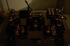
the last weeks brought some progress, both channels are up now and working nicely...

(Sorry for the image quality, no tripod at hand. Better pictures will follow!)
Now there's still some work left: finishing the input and output wiring, fitting the last panel with some status lights and get a housing done...
But it was really nice to throw the switch and get some music...
Regards,
Andreas
the last weeks brought some progress, both channels are up now and working nicely...
(Sorry for the image quality, no tripod at hand. Better pictures will follow!)
Now there's still some work left: finishing the input and output wiring, fitting the last panel with some status lights and get a housing done...
But it was really nice to throw the switch and get some music...
Regards,
Andreas
Attachments
Another step forward...
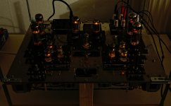
... this weekend: The input and output wiring is finished...

Now, only one panel is missing (middle front), three indicator lights will be mounted there to indicate HV enabled, B+ left up, B+ right up. They are powered from an unused 5V winding and switched via the auxiliary contacts two relays directly powered from the B+ rails. The relays switch on the heaters of the EZ81 for the negative rail as soon as both B+ are up.
A nice result: Although there is not yet a full enclosure, the amp is absolutely quiet with no signal present. No hum, no noise even with the ear close to the speaker.
Only a slight hum is audible from the power transformer, it vibrates more than expected. Hope to get that damped a little with the housing design...
Kind regards,
Andreas
... this weekend: The input and output wiring is finished...
Now, only one panel is missing (middle front), three indicator lights will be mounted there to indicate HV enabled, B+ left up, B+ right up. They are powered from an unused 5V winding and switched via the auxiliary contacts two relays directly powered from the B+ rails. The relays switch on the heaters of the EZ81 for the negative rail as soon as both B+ are up.
A nice result: Although there is not yet a full enclosure, the amp is absolutely quiet with no signal present. No hum, no noise even with the ear close to the speaker.
Only a slight hum is audible from the power transformer, it vibrates more than expected. Hope to get that damped a little with the housing design...
Kind regards,
Andreas
Attachments
Hi there,
I thought I might give an update:
The amp is running fine now, I prepared the structural parts of the housing and put the finished chassis in. Still got to do some stress testing with a new 5AR4 rectifier, I replaced the second JJ with a Sovtek to have the same rectifier tubes in both channels. But after some spark-ling experiences with JJ and Sovtek 5AR4 in the (admittedly demanding) power supply there will be some testing before the amp is moved to the living room for temporary use.
Current state of the project:

In operation:

Next steps:
1. Make a nice wooden frame around the basic MDF housing.
2. Find a manufacturer of high quality potentiometer knobs.
2. Finish the top plate to cover the whole thing nicely.
Regards,
Rundmaus
I thought I might give an update:
The amp is running fine now, I prepared the structural parts of the housing and put the finished chassis in. Still got to do some stress testing with a new 5AR4 rectifier, I replaced the second JJ with a Sovtek to have the same rectifier tubes in both channels. But after some spark-ling experiences with JJ and Sovtek 5AR4 in the (admittedly demanding) power supply there will be some testing before the amp is moved to the living room for temporary use.
Current state of the project:
In operation:
Next steps:
1. Make a nice wooden frame around the basic MDF housing.
2. Find a manufacturer of high quality potentiometer knobs.
2. Finish the top plate to cover the whole thing nicely.
Regards,
Rundmaus
So in 2023 it will be completed? [emoji6]
Hey!
It's been only 6 years now, I am quite confident it will be finished before the new Berlin airport opens. Construction work there started in 2006...
Rundmaus
So it finally happened.
I haven't been active in the forum for a while, maybe some older members might remember me.
But I just felt compelled to let you know that the longest and slowest project in the history of DIYaudio has finally concluded.
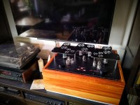
With the commissioning of a beautiful housing made by a local woodworking artist, my amplifier is finished after more than ten years into the project.
I'll make sexier pictures once it's off the workbench, but here's a first look. Enjoy!
Rundmaus


I haven't been active in the forum for a while, maybe some older members might remember me.
But I just felt compelled to let you know that the longest and slowest project in the history of DIYaudio has finally concluded.
With the commissioning of a beautiful housing made by a local woodworking artist, my amplifier is finished after more than ten years into the project.
I'll make sexier pictures once it's off the workbench, but here's a first look. Enjoy!
Rundmaus
- Home
- Amplifiers
- Tubes / Valves
- Rundmaus at work - PP1C without sand