To transducer
Hei transducer..
The pourpose of the 5 pf capacitor is to slow down the amplifier and inprove the fase margin (stability)...
You can bypass the D602 -604 but it can increased the tourn on bump!...(nothing is perfect)")
You can put a 10k Ohm resistor betwen the colector of Q604 and
the emiters of the long tail pair(this isolate the emiters of the LTP from the non linear output capacity of Q604.)
You.......................................................
More ideas!!!
Regards
Jorge Santos
Hei transducer..
The pourpose of the 5 pf capacitor is to slow down the amplifier and inprove the fase margin (stability)...
You can bypass the D602 -604 but it can increased the tourn on bump!...(nothing is perfect)
You can put a 10k Ohm resistor betwen the colector of Q604 and
the emiters of the long tail pair(this isolate the emiters of the LTP from the non linear output capacity of Q604.)
You.......................................................
More ideas!!!
Regards
Jorge Santos
You can also modify the output stage... use the schematic B on the picture. it inproves the turn off caracteristic of the output stage.
I made that change in my amplifier whit good results...
Here is a link to the doug self website with a lot of information about amplifiers: http://www.dself.demon.co.uk/dipa.htm#4
hope this help's
Regards
Rick
I made that change in my amplifier whit good results...
Here is a link to the doug self website with a lot of information about amplifiers: http://www.dself.demon.co.uk/dipa.htm#4
hope this help's
Regards
Rick
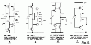
rickpt said:You can also modify the output stage... use the schematic B on the picture. it inproves the turn off caracteristic of the output stage.
I made that change in my amplifier whit good results...
hope this help's
Regards
Rick
Rick:
So in the Rotel schematic, I should substitute one resistor for R626/628, and bypass it with a capacitor? On Self's schematics, it seems like the new value resistor is a bit more than the total of the two original resistors. So in my case, would 500 ohms or so be good? And what value cap, at what voltage? In Self's Blameless Amp he uses 1uF (V??).
Can you describe the results when you modified your amp?
Thanks!
RonS
Re: To transducer
Jorge:
Would a better quality 5pF cap be worth installing?
Does bypassing D602/604 make any improvements? I have no turn on thumps right now!
I notice on Doug Self's amp, that he uses a 100R resistor on each emitter of the long tail pair connected to the collector of the current source. How do you determine the value of the resistor, and what would be the difference between using a single resistor to connect the collector of the current source to both the emitters in the long tail pairs, or using seperate resistors like Doug Self uses?
Thanks!
RonS
Tube_Dude said:Hei transducer..
The pourpose of the 5 pf capacitor is to slow down the amplifier and inprove the fase margin (stability)...
You can bypass the D602 -604 but it can increased the tourn on bump!...(nothing is perfect)
You can put a 10k Ohm resistor betwen the colector of Q604 and
the emiters of the long tail pair(this isolate the emiters of the LTP from the non linear output capacity of Q604.)
Jorge Santos
Jorge:
Would a better quality 5pF cap be worth installing?
Does bypassing D602/604 make any improvements? I have no turn on thumps right now!
I notice on Doug Self's amp, that he uses a 100R resistor on each emitter of the long tail pair connected to the collector of the current source. How do you determine the value of the resistor, and what would be the difference between using a single resistor to connect the collector of the current source to both the emitters in the long tail pairs, or using seperate resistors like Doug Self uses?
Thanks!
RonS
Different units, similar questions
Maybe some of you read my thread on a receiver I want to modify.
The power amp questions I raised are very similar to these on the Rotel amp.
Like whether some of Doug Self recipes will get a better sound, whether putting emitter resistors on the LTP or using certain arrangements or not.
Please note my accent on better sound instead of better specs.
But these matters of sound vs class AB or circuit design don't seem to attract as much attention as class A amps, apparently.
In my mind these matters were not settled. Modifying an existing equipment may not be original, but is certainly less expensive, less complicated and closer to many more people that want to improve on what they have. In the way making them more interested on building the whole thing in future projects.
Carlos
Carlos
Hi all,
First, my level of English is quite low, for that reason maybe I have not been able to explain to myself correctly, please, accept my excuses.
Then, my intention when adding a capacitor of 100uF is, in fact, to make a local filtering of the supply, not to improve the current source. I have read another time my E-mail and I think that it is this what says, but I repeat that I have not maybe been able to express it correctly.
Please, read about this in the chapter 8 of the Douglas Self book 'Audio Power Amplifier Design Handbook'.
Really, a RC filter should be used in the positive (100 Ohm, 100uF) and another RC filter in the negative (10 Ohm, 1000uF). Located immediately before the input differential.
I have made tests with this in some amplifiers Rotel (not exactly in their model) and, the TUMP! of the power on it was increased a lot, and I didn't like that.
After making several tests I found that, to add that capacitor of 100uF in that point, it improved the things a lot, besides being cheap.
I have limited myself to share with you this experience, but naturally you can to make their own tests and, if the filters RC works him better, then stupendous. If not, there will be you you amusing, and it can return whenever to the only capacitor.
I wait to have gotten to have expressed me well this time.
Happy days,
Raúl Couto
Hi Ron
The above statements about the turn-on hump are right (unless you have a turn-on-delay relay).
I didn't watch out for the behaviour of the two current sources invloved. The current source around Q608/Q610 will turn on faster than the one around Q604 if you bypass the two diodes and therefore cause momentary imbalance, leading to a turn-on hump. OTOH bypassing would improve noise and supply rejection a bit. I can't even say how much - since I never tried any circuit WITHOUT bypass on such current sources.
Jorge Santos' statement about the missing junction is right (collector of Q612 to base of Q618) as well. Since I assume your amplifier is working properly, this is only an error in the diagram.
The capacitor C616 is part of an inner feedback loop. Since it is not used outside the UK, I assume it isn't used to increase stability (which it also would be capable of) but might have been necessary to meet some EMC standrads (I don't know if British standards are more stringent then the rest of the world).
Regards
Charles
Charles,
Thanks for the clarifications
I think I'll try out some of the mods, bypassing D602/604. What value and voltage do you recommend?
The 5pF cap is used everywhere except for England. I'll upgrade that as well. While I changed out the input and feedback resistors to Vishay S102 (because I had the correct value lying about), I think the biggest improvement was made by changing the input cap, a weird little silver affair, rectangular in shape. For the moement I have a Solen metalized cap in there, but I want to try something a bit better.
I suspect that there is an error on the diagram, one day I'll trace it out on the board.
Thanks again for all of your help!
Best,
Ron
Hi Ron
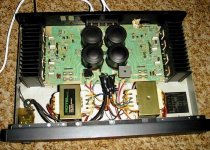
Now that I have seen the picture that has been posted by mpopovics I also see that there is no DC output protection relay. So one has to be careful with the size of a bypass capacitor.
I also see that there are fuses in the DC supply lines, so I think it would definitely be a good start to apply bypass capacitors after these fuses for both supply lines. I would try this one even before doing something on the current source. I think 100 uF (as Raul suggested) with low esr and reasonably high voltage rating would be a good starting point.
Regards
Charles
Hi Charles,
Yes, there are fuses in the DC rails. I didn't show the power supply schematic, maybe I should have Following the fuses, there is a 0.1uF cap to ground on each rail. I will upgrade these to something on the order of 100-1000uF, depending on what I can fit into this position. It is my understanding that while the fuses provide protection, they also increase the power supply impedence, not a good thing
There is no DC protection relay as you mentioned.
Speaking of rectifiers, as mpopovics brought it up, I'm thinking of going to Schottky rectifiers, as I've had good luck with them in the past. I can't find the spec's on the current bridge rectifier, but the fuses are rated at 4 amps and the power supply provides 41.6v after rectification, so we have approximately 30V AC on each leg of the secondary referenced to ground. I think that's correct, I should just measure. Any idea's for what rating I need for the Schottky rectifiers?
Regards,
RonS
Yes, there are fuses in the DC rails. I didn't show the power supply schematic, maybe I should have
Following the fuses, there is a 0.1uF cap to ground on each rail. I will upgrade these to something on the order of 100-1000uF, depending on what I can fit into this position. It is my understanding that while the fuses provide protection, they also increase the power supply impedence, not a good thing There is no DC protection relay as you mentioned.
Speaking of rectifiers, as mpopovics brought it up, I'm thinking of going to Schottky rectifiers, as I've had good luck with them in the past. I can't find the spec's on the current bridge rectifier, but the fuses are rated at 4 amps and the power supply provides 41.6v after rectification, so we have approximately 30V AC on each leg of the secondary referenced to ground. I think that's correct, I should just measure. Any idea's for what rating I need for the Schottky rectifiers?
Regards,
RonS
Rotel RB850 Corrected Schematic
I have been researching the Rotel RB850 amplifier for
several years.
I have redraw the schematic with some corrections based
on tracing a RB850, the schematic on this forum, and
schmatics of similar Rotel amps. The Rotel RA-02 is very
close to the same amp section. So are the 5-channel and
8-channel amps.
This site offers for free schematics of some similar
amps to the RB850.
www.eserviceinfo.com/browse.php?id=32
Sincerely,
Chris Browne
Ground Noise Industries
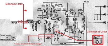
Rotel RB850 Birdging Switch
The schematic seems to have been floating
around for several years. It sure seems like
the small missing hole is the bridging switch
area from the other channel. Most other
Rotel amps have a resistor and cap from
the base of the input transistor to the
base of the second transistor of the
differential pair. I will have to retrace my
RB850 and see how the bridging switch
fits in the schematic. One amp will run
at 0 degrees and serve as the main
input and the second will run at
180 degrees out of phase and have
its original input disabled.
It seems logical. Your thoughts?
I hope to have
my amp back in September. . .
it has been on loan to a friend.
I have missed it though.
Chris
transducer said:........Rotel RB850 amplifier....... is this amp a good design or not?
As with many Rotel designs, this one has virtually nothing to recommend it.
Low-fi at its worst, i am afraid.

Bought one Rotel RB-956AX used.
Two pairs of outputs were gone, and one speaker terminal was broken.
Got hold of the original transistors and fixed everything. It works great.
But:
The Idle current in all the outputs were set to 160mA. I think this is quite high for this amp so i re-adjusted it to 100mA.
I am suspecting the previous owner turned it up for lower distortion, but this could be why it burned the two outputs.
Does any one know what the Idle current is supposed to be?
V=IR
If the output resistor is 0.22 ohms and you have 100 mA through it.,
then there is 22 mV across the resistor. 100 mA seems like an excessive amount of current at idle. I think mine is less than 10 mV across the 0.22 ohm output resistor resulting in 45 mA through the resistor. And that is up from about 6 mV from the factory. It runs warm, but sure made it sound not as harsh. . .
In class A, my Yamaha M-45 runs at 125 mA if I remember correctly.
- Status
- This old topic is closed. If you want to reopen this topic, contact a moderator using the "Report Post" button.
- Home
- Amplifiers
- Solid State
- Rotel RB850 Still Current? Schematic Included