Gentlemen,
I received a quote for the 2nd round of group-buy of the FC-100 today.
Since I do no more have to pay for tooling, I am able to offer you smaller prices for the PCBs.
I will offer you Rev.1 of the speaker-protection PCB in this round of group-buy.
Rev.1 improves the stability; you can fit the OMRON G2R-2A relay, the AMPLIMO, the ... on it.
Rev.1 is tested and approved.
But since Rev.1 needs tooling again, I have to raise its price a little bit.
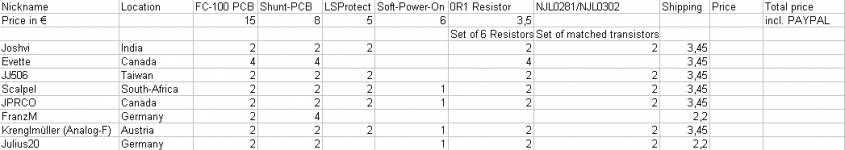
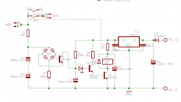
Concerning the OP-transistors: a pair of NJL0281DG/NJL0302DG costs about 5€ currently (MOUSER-price).
You need 3 pairs of these transistors per PCB.
I will match them for you (if you like).
In order to have a "bigger pool" for the matching process, I think that it is wise if you order 4 pairs per PCB.
That is why I calculated 20€ per PCB. I will of course include the spare transistors in your letters.
What about the Vishay MKP1839 capacitor? Do you know, where to get it?
What about authentic Toshiba 2SA1360 / 2SC3423? Where do you get them?
Is somebody of you able to match the 2SK170 as Mihai recommends?
Best regards - Rudi_Ratlos
I received a quote for the 2nd round of group-buy of the FC-100 today.
Since I do no more have to pay for tooling, I am able to offer you smaller prices for the PCBs.
I will offer you Rev.1 of the speaker-protection PCB in this round of group-buy.
Rev.1 improves the stability; you can fit the OMRON G2R-2A relay, the AMPLIMO, the ... on it.
Rev.1 is tested and approved.
But since Rev.1 needs tooling again, I have to raise its price a little bit.
Concerning the OP-transistors: a pair of NJL0281DG/NJL0302DG costs about 5€ currently (MOUSER-price).
You need 3 pairs of these transistors per PCB.
I will match them for you (if you like).
In order to have a "bigger pool" for the matching process, I think that it is wise if you order 4 pairs per PCB.
That is why I calculated 20€ per PCB. I will of course include the spare transistors in your letters.
What about the Vishay MKP1839 capacitor? Do you know, where to get it?
What about authentic Toshiba 2SA1360 / 2SC3423? Where do you get them?
Is somebody of you able to match the 2SK170 as Mihai recommends?
Best regards - Rudi_Ratlos
Attachments


Maybe it's time to buy the last pieces from the market.
")
Patrick,
the max. grid of the input DC-blocking input capacitor is 15mm.
Everybody has to decide by himself, if he needs an input-cap at all.
If he is sure that all of his music - sources are AC-coupled, he doesn't need.
If not:
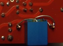
I recommend to use of MKT1822 bypassed by MKP1837.
I use this combination myself: I "glued" the MKP on the solder-side and then soldered it.
The value: max. value with a grid of 15mm.
Do you have any other recommendation?
Best regards - Rudi
the max. grid of the input DC-blocking input capacitor is 15mm.
Everybody has to decide by himself, if he needs an input-cap at all.
If he is sure that all of his music - sources are AC-coupled, he doesn't need.
If not:
I recommend to use of MKT1822 bypassed by MKP1837.
I use this combination myself: I "glued" the MKP on the solder-side and then soldered it.
The value: max. value with a grid of 15mm.
Do you have any other recommendation?
Best regards - Rudi
Attachments
I used this one: IT-Tronics - 5x MKT Kondensator radial 10uF 100VDC RM27,5 ; RoHS ; 1822610015
they will be 5€ for five pieces ( Roederstein MKT1822/100V )
they will be 5€ for five pieces ( Roederstein MKT1822/100V )
If you can find an old stock polycarbonate folded film (rather than wound) then it is almost as good as polypropylene at half the price and half the size.
I think the carbonates are better than the various esters and terephthalates.
I think the carbonates are better than the various esters and terephthalates.
Polyethylene terephthalate (sometimes written poly(ethylene terephthalate)), commonly abbreviated PET, PETE, or the obsolete PETP or PET-P,
Julius, the 10µF MKT1822 has a grid of 27.5mm , whereas the PCB offers space for a 15mm grid capacitor only.
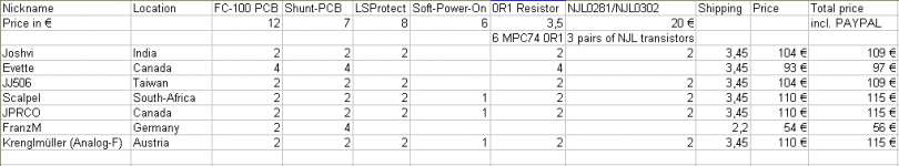
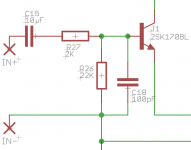
The input capacitor C15 blocks DC; together with resistor R26 it defines a highpass - filter.
It is not essential to use a 10µF on this position. I myself use a 2.2µF MKT1822.
And, please remember: "The best filter is no filter at all!" Mihai does not use this capacitor in his original schematics!
Maybe all of your music-sources are already AC coupled: then you need not install C15 but use the jumper.
For me, it is a "Must have", because I am DIYing all kind of music-sources (Pre-AMPs, DACs, ...), and maybe that one of my builds is not working properly.
Anto: you are very welcome!
Jean: maybe, I never tested this, but I would not use the NJL1302D/NJL3281D pair of transistors.
The reason why: the output capacitance (COB) of the pair of NJL1302D/NJL3281DG is much higher (600pF) compared to the COB
of a pair of NJL0302D/NJL0281D, which is 400pF.
The drivers have to load/unload this excess of capacitance, and I am afraid that this will affect the overall operation.
Perhaps somebody else knows it better.
Best regards - Rudi_Ratlos
P.S. Andrew: thank you for your hint.
Attachments
Last edited:
Don't make the input cap too big.
The filter, if you decide to fit it, must set the LF bandwidth.
That bandwidth MUST be properly amplified by the Power Amplifier.
That requires all the following filters to be wider band than the input filter.
Even the PSU filter must be wider than the input filter.
Your sch shows 10uF and 22k+2k for a 240ms time constant.
That gives a F-3dB = 0.66Hz.
That would require that the amplifier can handle frequencies down to that level.
A 3u9F or 3u6F would suit me. Try it. Even 3u3//22n might be good enough.
- Status
- This old topic is closed. If you want to reopen this topic, contact a moderator using the "Report Post" button.
- Home
- Group Buys
- Roender's FC-100 Rev.1 Group-Buy