Similar problem
I had a similar issue with one of my resistors. I suspect that the problem is due to too much heat applied when I soldered it in place. I would replace the resistor. Better safe than sorry.
Also, there is a fine grit that comes out of the loosened resistor. I also recommend you look for that and thoroughly clean the board.
I tend to take a more cautious approach to these things. YMMV.
Ryan
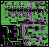
I have finally finished the layout of the "supplementary audio PCB" and have ordered a prototype PCB:
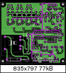
The size of the PCB is 100 x 100 mm and it includes:
- a 3-source selection (top left)
- a mute relais
- George Stantscheff's Lightspeed Attenuator (top right)
- 2 temperature sensors (LM35) (below the attenuator)
- LCD connectivity
- infrared sensor
- Motor-H - bridge (for motorized potentiometer adjusting the attenuator, on the bottom)
The heart / brain of the PCB is included in a PIC 16F886 µProcessor, and the PCB's functionality is controlled by an infrared remote control unit.
This PCB is of course intended to work together with my FC-100.
I do not yet have much experience with the programming of µProcessors, but I will learn it, and maybe, in a month or so,
I will be able and offer you (if you like) this PCB.
Best regards - Rudi_Ratlos
P.S. John, Ryan: I have never had any problems soldering MPC74 - type - resistors.
Attachments
Ok since this is the builders thead I have a question about those elusive 2.2R resistors.
How much tolerance can the circuit stand without ANY degrade in performance or stability?
I'm asking this because maybe we can find 2.21R or 2.1R from the usual sources.
On a different project I'm working on presently, I changed .47 output resistors with .5 to get them of a better quality.
How much tolerance can the circuit stand without ANY degrade in performance or stability?
I'm asking this because maybe we can find 2.21R or 2.1R from the usual sources.
On a different project I'm working on presently, I changed .47 output resistors with .5 to get them of a better quality.
Ok since this is the builders thead I have a question about those elusive 2.2R resistors.
How much tolerance can the circuit stand without ANY degrade in performance or stability?
I'm asking this because maybe we can find 2.21R or 2.1R from the usual sources.
On a different project I'm working on presently, I changed .47 output resistors with .5 to get them of a better quality.
Anything between 2 and 3 ohm will be ok.
Anything between 2 and 3 ohm will be ok.
I did another search on Mouser up to 2.5 ohm, and still nothing available. I had to up the power to 1W to find something.
If you can/like mount vertical there are a few that could work.
This is the closest match:
CPF12R2100FKB14 Vishay/Dale | Mouser
Hope this could help u guys.
I did another search on Mouser up to 2.5 ohm, and still nothing available. I had to up the power to 1W to find something.
If you can/like mount vertical there are a few that could work.
This is the closest match:
CPF12R2100FKB14 Vishay/Dale | Mouser
Hope this could help u guys.
hmmm, then you maybe looked in the wrong place!
here you go: cmf552r Metal Film Resistors - Through Hole | Mouser
shows all CMF55 between 2-3Ohm which can be ordered at the moment at mouser!
Anything between 2 and 3 ohm will be ok.
roender, what would be the "better" solution instead of the 2R2?
2 Ohm
or
2,87 Ohm
thank you.
hmmm, then you maybe looked in the wrong place!
here you go: cmf552r Metal Film Resistors - Through Hole | Mouser
shows all CMF55 between 2-3Ohm which can be ordered at the moment at mouser!
Ahem,
wasn't the resistor specified for half watt? You can go higher but not lower (it causes higher distortion, provided it doesn't burn).
Ahem,
wasn't the resistor specified for half watt? You can go higher but not lower (it causes higher distortion, provided it doesn't burn).
CMF55 is half watt. look at the datasheet. it`s 0,5W @ 70° and 0,25W @120°
when you compare them with other datasheets like other Vishay or PRP you see the all refer to 70°


Could someone help me and explain how to use the testing/matching circuit presented on Buiders manual Page 22 in order to measure Hfe and Vbe for:
2SC3423Y/2SA1360Y
MJE15034/MJE15035
NJL0281/0302
For To-92 transistors i have a DMM with hfe measuring capability.
Thanks!
Adrian
2SC3423Y/2SA1360Y
MJE15034/MJE15035
NJL0281/0302
For To-92 transistors i have a DMM with hfe measuring capability.
Thanks!
Adrian
- Status
- This old topic is closed. If you want to reopen this topic, contact a moderator using the "Report Post" button.
- Home
- Amplifiers
- Solid State
- Roender's FC-100 prototype and builder's thread