Mihai,
I have measured the diode's VF on "the fly".
The AMP is running since half an hour.
The voltage that drops across any diode is 500mV.
Best regards - Rudi
It has 30mV more! They definitely had changed the thermal compensation diode!
If the diode TC is not anymore -1.6mV/grdC and is around -2.1mv/grdC then your output is perfectly thermal compensated with only four diode into the string.
You can easily check that by measuring the stability of the voltage dropped over one Re when the amplifier is cold and hot. Should not drift more than 1..2mV
Last edited:
another possibility is a manufacturing "defect". i believe charles hansen mentioned a while ago (maybe in the thermal trak thread?) that his company purchased some parts that were manufactured with the "wrong" diode installed. maybe rudi got hold of some of those parts ...
mlloyd1
mlloyd1
It is just a supposition ... I do not know if is true.
What happened with Rudi's amplifier is very strange because he didn't change anything in RMI-FC100 design.
another possibility is a manufacturing "defect". i believe charles hansen mentioned a while ago (maybe in the thermal trak thread?) that his company purchased some parts that were manufactured with the "wrong" diode installed. maybe rudi got hold of some of those parts ...
mlloyd1
Could be just that. Charles Hansen used NJL3281/1302 into Ayre MX-R power amplifier. Maybe the same mistake apply to zero version of NJL's too.
You are right, Mihai.
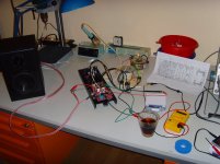
The AMP is playing for some time now (see image below).
I am continously measuring the voltage that is dropping across a specific emitter resistor: the voltage remains between 21 - 23 mV.
Best regards - Rudi
The AMP is playing for some time now (see image below).
I am continously measuring the voltage that is dropping across a specific emitter resistor: the voltage remains between 21 - 23 mV.
Best regards - Rudi
Attachments
Last edited:
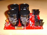
Since the "ThermalTrack-Diode-Issue" seems to be resolved now (I will of course implement the resolution into the FC-100 Version1 - layout),
I will now find out, if a "high-sophisticated" external PSU (Carlos' DX PSU: 30.000µF per rail, C-L/R -C filter, see picture attached) will improve
the sound or if I will leave the on-board PSU.
Best regards - Rudi
I will now find out, if a "high-sophisticated" external PSU (Carlos' DX PSU: 30.000µF per rail, C-L/R -C filter, see picture attached) will improve
the sound or if I will leave the on-board PSU.
Best regards - Rudi
Attachments
Since the "ThermalTrack-Diode-Issue" seems to be resolved now (I will of course implement the resolution into the FC-100 Version1 - layout),
I will now find out, if a "high-sophisticated" external PSU (Carlos' DX PSU: 30.000µF per rail, C-L/R -C filter, see picture attached) will improve
the sound or if I will leave the on-board PSU.
Best regards - Rudi
Are you sure is resolved? Did you blow very hot air over the output transistors and the voltage over the Re didn't changed much? Did you played near to clipping music for a long period of time and measure the same voltage very quickly after the music stops to see if the recover period is under 1 or 2 seconds?
Are you sure you don't have an runaway bastard?

Thermal runaway beast
Yesterday I tortured the prototype with a 500 Hz sinus wave, being played at maximum volume of my MP3-player,
using an 8 Ohm / 100 watt resistor as the speaker's load.
Within 15 minutes the voltage that dropped across the measured emitter resistor increased to 40 mV and the voltage
that dropped across the unused 6th internal diode decreased to about 410 mV.
This is near "thermal death" and I aborted the torture.
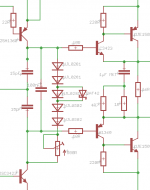
A German DIY-friend gave me the hint to bypass one of the used internal diodes by a SCHOTTKY diode.
Compared with the internal silicon thermal track diode the BAT42 SCHOTTKY diode has a much lesser forward voltage drop
and has a negative temperature coefficient as well.
The temperature compensation now looks like on the image attached.
After bypassing one of the 5 used internal diodes by the SCHOTTKY, the initial value of the voltage that drops across
the measured emitter resistor is now 4 mV with the trimm-resistor's value preset to 0 Ohm.
I can of course adjust the value to 20-21 mV.
I will now solder the SCHOTTKY so that the diode is in close contact with the heatsink and will very carefully restart the 500 Hz torture test.
Best regards - Rudi_Ratlos
Yesterday I tortured the prototype with a 500 Hz sinus wave, being played at maximum volume of my MP3-player,
using an 8 Ohm / 100 watt resistor as the speaker's load.
Within 15 minutes the voltage that dropped across the measured emitter resistor increased to 40 mV and the voltage
that dropped across the unused 6th internal diode decreased to about 410 mV.
This is near "thermal death" and I aborted the torture.
A German DIY-friend gave me the hint to bypass one of the used internal diodes by a SCHOTTKY diode.
Compared with the internal silicon thermal track diode the BAT42 SCHOTTKY diode has a much lesser forward voltage drop
and has a negative temperature coefficient as well.
The temperature compensation now looks like on the image attached.
After bypassing one of the 5 used internal diodes by the SCHOTTKY, the initial value of the voltage that drops across
the measured emitter resistor is now 4 mV with the trimm-resistor's value preset to 0 Ohm.
I can of course adjust the value to 20-21 mV.
I will now solder the SCHOTTKY so that the diode is in close contact with the heatsink and will very carefully restart the 500 Hz torture test.
Best regards - Rudi_Ratlos
Attachments
Last edited:
Finally I tamed the beast
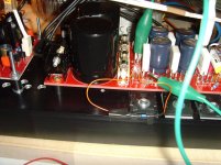
I soldered the SCHOTTKY -bypass diode this morning and once more tortured the FC-100.
The temperature compensation diode string now consists of 4 internal thermal track diodes and an external SCHOTTKY diode,
which is in close contact to the heatsink.
I connected my 8 Ohm / 100 Watt resistor network to the AMP and played a 500 sine Hz wave at full volume once more.
The heatsink got very, very hot after 30 minutes.
Then I shut the sine wave input down, and the voltage that dropped across the emitter resistor that I have been measuring all the time,
dropped to 20.8 mV in the same second.
Did the additional SCHOTTKY diode tame the "thermal runaway"?
I am very sure that it does!
The 4 internal + 1 external diode string performs better than the 4-internal-diode string only that I have measured yesterday!
Allthough: the 4-internal diode string wasn't that bad either!
I will make provisions and incorporate an external SCHOTTKY diode (in a TO220 case, if it is needed at all!) on the final PCB.
In my eyes this PCB / AMP is playing "stable like a rock" and I give it a "Go".
But I will wait for ZSAUDIO's experiences, who is currently building the 2nd prototype, nevertheless.
Best regards - Rudi_Ratlos
P.S I will start and solder the 2nd channel right now.
Attachments
Last edited:
Hi Rudi,
could you also torture the amp with square wave and capacitive load to test stability ?
perhaps also triangle wave to test linearity.
http://www.diyaudio.com/forums/solid-state/100669-testing-stability.html
http://www.diyaudio.com/forums/solid-state/116771-linearity.html#post1420238
could you also torture the amp with square wave and capacitive load to test stability ?
perhaps also triangle wave to test linearity.
http://www.diyaudio.com/forums/solid-state/100669-testing-stability.html
http://www.diyaudio.com/forums/solid-state/116771-linearity.html#post1420238
@PeterLeest you were a bit quicker than me, on the Stability and linearity testing. I am interested also.
Do you think clipping and stability testing a dead and active load with a scope is worth a try, or apply? This way we can see square, clipping, and crossover notch. Just out of interest. Found some basic links below see if you think it is worth it. They have some sine and square stuff.
Reference:
http://www.diyaudio.com/forums/solid-state/100669-testing-stability.html
http://www.diyaudio.com/forums/pass-labs/207777-just-starting-learn-o-scope-f5-1k-square-looks-funny.html
One board switched on.
I use 5 TC diodes. I can set my bias from about 6mV up to the desired 18-21mV across 0,1R Re. I did not watch for the max current.
My backend PSU voltage is +/-30V DC because i do not have any trafo with 2×25V secondaries.
Output DC offset is about 0,1-0,15 mV
I'll do more test tomorrow.

zsaudio
I use 5 TC diodes. I can set my bias from about 6mV up to the desired 18-21mV across 0,1R Re. I did not watch for the max current.
My backend PSU voltage is +/-30V DC because i do not have any trafo with 2×25V secondaries.
Output DC offset is about 0,1-0,15 mV
I'll do more test tomorrow.
zsaudio


@PeterLeest
I tested with a 1 KHz square-wave as well.
I did not see any oscillation on the scope. No problem.
A very interesting feature of this AMP is: no "crack", while turning power-on and no hiss or "SCHSSsssssss" during power-off.
Carlos' DX AMPs (the ones that I built) and Michael Bittner's SYMASYM have at least the "SCHSSsssssss" during power-off.
I am looking forward to ZSAUDIO's experiences with this AMP.
Congratulations, Zsolt, to your build!
Best regards - Rudi_Ratlos
Yes, pretty interesting, post 725, gives some ideas on the "thump" start up.
http://www.diyaudio.com/forums/soli...age-audio-power-amplifier-73.html#post1772273
http://www.diyaudio.com/forums/soli...age-audio-power-amplifier-73.html#post1772273
@PeterLeest
I tested with a 1 KHz square-wave as well.
I did not see any oscillation on the scope. No problem.
A very interesting feature of this AMP is: no "crack", while turning power-on and no hiss or "SCHSSsssssss" during power-off.
Carlos' DX AMPs (the ones that I built) and Michael Bittner's SYMASYM have at least the "SCHSSsssssss" during power-off.
I am looking forward to ZSAUDIO's experiences with this AMP.
Congratulations, Zsolt, to your build!
Best regards - Rudi_Ratlos
That's nothing compared with how it sound
Guys, I'll bet this will be your ultimate amplifier. Look after better speakers, sources and forget power amp because this is almost a wire with gain
- Status
- This old topic is closed. If you want to reopen this topic, contact a moderator using the "Report Post" button.
- Home
- Amplifiers
- Solid State
- Roender's FC-100 prototype and builder's thread