Andrew,
the current status is:
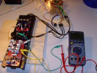
Input short, 4 diodes activated, VR adjusted to 18mV emitter-resistor voltage drop, no load on the output.
I waited 10 minutes to get the temperatures "settled".
Then I measured the following voltages:
Pre-Driver 2SC3423 (NPN)
Emitter: 595mV
Collector: 26.5V
Base: 1.14V
Driver MJE15035 (PNP)
Base: 27.2V
Collector: 600mV
Emitter: 27.7V
Pre-Driver 2SA1360 (PNP)
Emitter: -600mV
Collector: -27V
Base: -1.15V
Driver MJE15034 (NPN)
Base: -27V
Collector: -590mV
Emitter: -27.4V
Best regards - Rudi
the current status is:
Input short, 4 diodes activated, VR adjusted to 18mV emitter-resistor voltage drop, no load on the output.
I waited 10 minutes to get the temperatures "settled".
Then I measured the following voltages:
Pre-Driver 2SC3423 (NPN)
Emitter: 595mV
Collector: 26.5V
Base: 1.14V
Driver MJE15035 (PNP)
Base: 27.2V
Collector: 600mV
Emitter: 27.7V
Pre-Driver 2SA1360 (PNP)
Emitter: -600mV
Collector: -27V
Base: -1.15V
Driver MJE15034 (NPN)
Base: -27V
Collector: -590mV
Emitter: -27.4V
Best regards - Rudi
I have already been told that my voltage measurements are not "reliable".
For example: the voltage measured at the collector of Q19 (pre-driver SC3423) must be the same as the voltage at the base of Q3 (driver MJE15035).
I have just switched on the AMP again and let it settle within the next 30 minutes.
I will then measure again.
Best regards - Rudi_Ratlos
For example: the voltage measured at the collector of Q19 (pre-driver SC3423) must be the same as the voltage at the base of Q3 (driver MJE15035).
I have just switched on the AMP again and let it settle within the next 30 minutes.
I will then measure again.
Best regards - Rudi_Ratlos
Andrew,
I measured once more after 45 minutes:
MJE15034: Base: -26.29V, Collector: -583mV, Emitter: -26.8V
2SA1360: Emitter: -583mV, Collector: -26.24V, Base: -1.113V
MJE15035: Base: 26.08V, Collector: 587mV, Emitter: 26.58V
2SC3423: Emitter: 587mV, Collector: 25.92V, Base: 1.114V
There is some measuring inaccuracy; this is inevitable.
Bes regards - Rudi
Pre-Driver 2SC3423 (NPN)
Emitter: 595mV
Collector: 26.5V
Base: 1.14V
Pre-Driver 2SA1360 (PNP)
Emitter: -600mV
Collector: -27V
Base: -1.15V
the base to base voltage of the pre-drivers is 2.29V in the first measurements.2SA1360: Emitter: -583mV, Collector: -26.24V, Base: -1.113V
2SC3423: Emitter: 587mV, Collector: 25.92V, Base: 1.114V
The voltage across the bases of the pre-drivers has changed to 2.227V
This shows that the diodes are changing the bias voltage as the outputs heat up.
If the 2.3mA of bias current stays constant then we see that the diode string has changed from 2.29-0.38V to 2.227-0.38 in the two sets of measurements.
You can measure this voltage directly on the PCB. Find locations so that a probe slip does not blow up the amplifier.
BTW,
2.227-0.38 gives ~ 462mVf across each diode. This seems about right for a diode passing only 2.3mA
Are you using the same NJLs as Roender?
Last edited:
Yes, Andrew, I use NJL0281 / NJL0302 with integrated ThermalTrack diodes.
Maybe my ones are not as perfectly matched as Mihai's.
The following questions remain:
Why am I not able to activate the 5th diode?
Will a 4-diode string be safe enough for temperature compensation?
Remember: I am currently using only 4 integrated diodes; I shorted the 5th one.
I will wait for the results of ZSAUDIO's prototype.
Best regards - Rudi_Ratlos
Why am I not able to activate the 5th diode?
Will a 4-diode string be safe enough for temperature compensation?
Best regards - Rudi_Ratlos
This is a very strange issue! Everything it's looking just fine and I have no idea why you are not able to insert the 5th diode.
With only 4 diodes string the output stage will be lightly under compensated. Please test how will performs in cold and hot situations from Vre drop point of view ... otherwise everything looks good.
ZDR,
I (the layout) bypassed the last TT-diode (of transistor Q4) in the string.
I will change the final layout of the PCB to include jumpers on the diodes.
It will then be possible to bypass another diode, but this is impossible with the current layout.
Best regards - Rudi
I (the layout) bypassed the last TT-diode (of transistor Q4) in the string.
I will change the final layout of the PCB to include jumpers on the diodes.
It will then be possible to bypass another diode, but this is impossible with the current layout.
Best regards - Rudi
I over-drilled the pads of one diode location on the original PCB.
Then insulated the two diode leads to pass through these over-drilled holes.
Left the diodes leads long for a future use, eg temperature monitor to activate a warning light or klaxon or over-temp power off.
Shorted across the remains of the two pads with a 0.4mm diam tinned copper lead, to complete the diode string route.
Maybe it's time to experiment with different value emitter resistors, now that there are no glaring errors found. Mihai designed the amp with .1 ohm resistors. This would create a larger standing current at idle, thus creating a higher idle temperature in the output transistors, and thus a different voltage across the diodes at idle. If you drop to .1 ohm, make sure that you have adequate heat sinking, and don't forget to remove the shunt you added across one of the diodes. Perhaps at this higher idle temperature, the fifth diode would result in a similar bias spread as you have now.
But before doing this, why not give the amp a listen?
But before doing this, why not give the amp a listen?
Last edited:
Neb, I played around this morning and added an additional 0R22 in parallel to the already existening 0R22 emitter-resistors,
resulting in a value of 0R11.
There was only a very slight progress.
In order to adjust the bias in the 4-diode version to 18mV, the value of the Vr is now 195 Ohm (instead of 165 Ohm with 0R22).
And: with an initial value of 0 Ohm of the Vr, the 5-diode version now shows a initial value of 35mV voltage drop across an 0R1 emitter-resistor
(compared to 45mV with the 0R22 version).
I do stop now with my experiments.
I will connect a cheap speaker to the output and listen how the AMP sounds.
I am looking forward to ZSAUDIO's results.
Best regards - Rudi_Ratlos
Attachments

try reducing the current through the diode string.
As a first experiment add a 1k across one diode. This will bypass ~0.4mA and result in ~1.9mA through the diode.
If this reduces the voltage across the whole string and reduces the voltage across the emitter resistors then add a resistor across a second diode.
That 2.3mA is higher than Roender's 2mA of diode bias.
18mV to 19mV of Vre is specifically for 0r1.
If you change the RE to 0r11 then Vre also increases slightly for the same output bias conditions, (similar amounts of crossover distortion).
Changing Re to 0r22 requires a much higher Vre for the same crossover distortion reduction, probably around 21mVre to 23mVre.
BTW,
1r0//0r22//0r22~=0r991
This is a typo, isn't it? 1R0//0R22//0R22~=0R0991BTW,
1r0//0r22//0r22~=0r991
What about adding a 3k9 across the entire diode string? Or a trimmpot?
Last edited:
I have allot of basics to catch up on and learning as I go, so don't derail your thoughts due to my question. Is this similar to the types of issues they try to solve with a bias spreader?
thermaltrak thread
http://www.diyaudio.com/forums/soli...al-compensation-thermal-trak-transistors.html
Seems to implement bypass and other bias methods
http://www.pansonaudio.com/Docs/Kits/Initial%20Power%20Amp/App%20Note%20101%20rev1p2.pdf
ThermalTrak
http://www.diyaudio.com/forums/solid-state/182554-thermaltrak-tmc-amp-3.html#post2751316
and post #19
Andrew,
this would have been a very clever idea - if it had worked!
What I did:
I unsoldered the additional 0R22 emitter resistors that I have soldered this morning (now having no more 0R11 but 0R22 emitter resistors)
and "bypassed" (soldered in parallel) 2 diodes with 500 Ohm resistors.
The result:
With the trimm-resistor's value of 0 Ohm the initial value of any emitter-resistor is about 30 mV (no more 45 mV).
But I still can't adjust the emitter resistors' voltage drop to 18-21 mV.
I will try FranzM's suggestion now.
Best regards - Rudi
P.S.
@wtm111: I am sure that we will get this problem fixed.
Last edited:
With resitors the current diverted from the bias string will vary with temperature as the bias voltage varies with temperature. This will alter the temperature compensation. So the current diverting network should have a somewhat similar thermal behavior. Maybe one could use a series string consisting of a resistor and one or more small signal diodes connected across C7. The question is where to place these diodes (on which side of the pcb).
It would be easier to change R15 and R19 to achieve the right current values (assuming this is the real cause of the problem). Or my suggestion from post #215.
However, a bias method that sensitive to VAS current could cause some trouble.
Let's see if Mihai has some experience with this.
It would be easier to change R15 and R19 to achieve the right current values (assuming this is the real cause of the problem). Or my suggestion from post #215.
However, a bias method that sensitive to VAS current could cause some trouble.
Let's see if Mihai has some experience with this.
Last edited:
- Status
- This old topic is closed. If you want to reopen this topic, contact a moderator using the "Report Post" button.
- Home
- Amplifiers
- Solid State
- Roender's FC-100 prototype and builder's thread