yea it was a solder joint on one of the resistors; I redid all of my solder joints and signal is back but its still only 5v.
think the value of one of the resistors I added in could be making the drive voltage low?
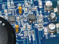
R231 234 and 235 have been replaced with correct value 1/4 watt 5% resistors at 2kohm (2x 1k in series), 2.7ohm, 100ohms respectively. All values match what the schematics have on them and they also match what their sister resistor values are. (all resistors were tested before i soldered them in too)
think the value of one of the resistors I added in could be making the drive voltage low?
R231 234 and 235 have been replaced with correct value 1/4 watt 5% resistors at 2kohm (2x 1k in series), 2.7ohm, 100ohms respectively. All values match what the schematics have on them and they also match what their sister resistor values are. (all resistors were tested before i soldered them in too)
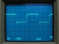
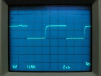
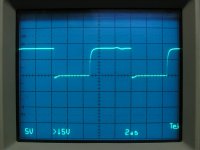
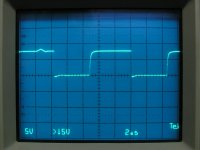
Confirm that you have the same signal levels on the cathodes of D207 and D207. The first two are D207/208 with the differential probe setup and the ch2 probe on the collector of Q203. The second ones are with a single probe but with the collector of Q203 shorted to the negative speaker terminal.
Attachments
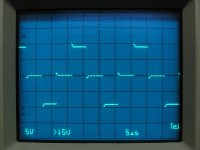

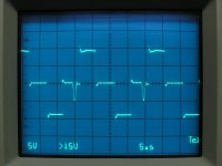
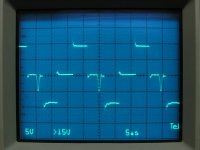
These are the base and emitter waveforms for Q203 (first two) and Q206. Hold the cursor over the thumbnail to see the filenames. It appears that Q203 may be weak.
This was taken with the differential probe setup (collector of Q203 as the reference). The bottom of each waveform was aligned with the reference to make it easier to see the true amplitude.
This was taken with the differential probe setup (collector of Q203 as the reference). The bottom of each waveform was aligned with the reference to make it easier to see the true amplitude.
Attachments
Last edited:
got all the new fets and such in the mail today going to try and put them in tonight or tomorrow and hopefully not blow them up.... if the first set dies i'll buy the ones that rf used in the later amps but these were cheap and i have an idea how to use the rest if the first set dies...
anyway the caps i ordered were the same on paper, 4.7uf 250v mylar/nylon wahtever caps like the one that came out but the ones i got are half the physical size of the original. will this be a problem? both weigh about the same; the smaller one is definately mroe dense and less blown up than the original lol
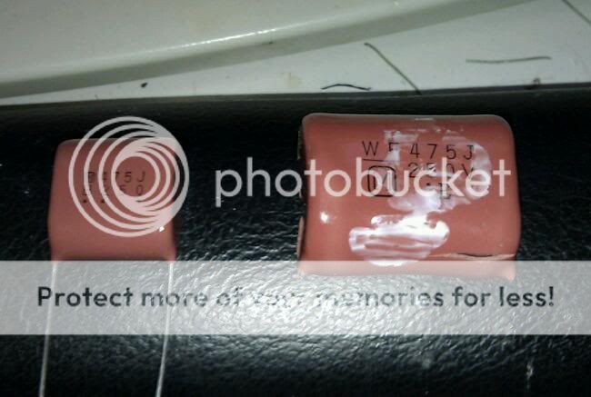
anyway the caps i ordered were the same on paper, 4.7uf 250v mylar/nylon wahtever caps like the one that came out but the ones i got are half the physical size of the original. will this be a problem? both weigh about the same; the smaller one is definately mroe dense and less blown up than the original lol
Well I replaced all the output fets and C242 powered it up and all seemed well but as soon as the amp unmuted something brought down the power supply (like a high load) and would cycle doing that about 2/sec.
Q208/Q209 got warm after a few seconds of doing that; much warmer than the rest of the fets
this waas with no load and no input and all 8 output fets installed
Q208/Q209 got warm after a few seconds of doing that; much warmer than the rest of the fets
this waas with no load and no input and all 8 output fets installed
did not tin them and did not mount them to the insulator; is that part of the curciut?
i think its the fets not suited; just removed them all they all check out ok and all the waveforms are still good on the gate pins with no output fets...
i looked at the turn on and turn off times of this new fet and its TERRIBLE compared to the old ones; i'll have to post up exactly but i think it was just too slow...
i also had some nasty RFI when they were in; enough to make noise out of my speaker and make my crt monitors flicker slightly
those dont get hot at all, the amp was on maybe 5sec while popping, i removed 208/209 to look at the wave forms and the rfi got worse and the wave forms looked all kinds of messed up...
all output fets are out now; i'm going to order the correct ones monday and try agian.
all output fets are out now; i'm going to order the correct ones monday and try agian.
- Status
- This old topic is closed. If you want to reopen this topic, contact a moderator using the "Report Post" button.
- Home
- General Interest
- Car Audio
- Rockford T10001BD blown output fet