R234 was NOT within spec. it measured about 940ohms on curcuit while its sister resistor on the other side (r254 iirc dont have schematic handy on my notebook) measured about 1980ohm; i pulled that resistor to measure it off the board and dropped it into the carpet never to be seen again 
at that point i gave up for the day and made dinner lol....
tomorrow i'm going to replace r234 with a 2k ohm 1% surface mount i can hopefully scavange from something or probably 2x 1kohm resistors in series hovering above the board like Q206 is...
Also would leaving the long legs on Q206 cause any problems?
i thought about shortening them to let the transistor sit closer to the board but i couldn't find anything to insulate the 2 pins i had to twist
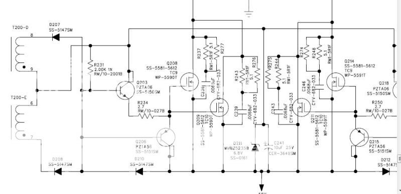
you sure? the marking was "2001" and in the version 5 schematic which is closest to the amp i am working with says 2k 1% iirc
unless we're talking about 2 different resistors here... i'm talking about the one that goes from the center tap on the drive trafo secondary to the gate on Q206.... i'm going off memory now so i may be off
unless we're talking about 2 different resistors here... i'm talking about the one that goes from the center tap on the drive trafo secondary to the gate on Q206.... i'm going off memory now so i may be off
ok so r234 was open. i replaced that and r231 with some 1/4 watt non surface mount resistors i had (2k and 2.7ohm respectively).
went to power it on and i think it caused a few output fets to fail immidiately power supply buzzed ilike it was shorted and now a few outputs read 0 ohms accross the source and drain... even on q211-214 some failed; and those were good before and i haven't touched that side of the drive curciut.
i removed them and all the output fets have good looking wave forms on them....
does this go back to what you were saying parry that you can't swap out output fets on a class d to just anything?
went to power it on and i think it caused a few output fets to fail immidiately
power supply buzzed ilike it was shorted and now a few outputs read 0 ohms accross the source and drain... even on q211-214 some failed; and those were good before and i haven't touched that side of the drive curciut.i removed them and all the output fets have good looking wave forms on them....
does this go back to what you were saying parry that you can't swap out output fets on a class d to just anything?
Last edited:
four failed and four were good...
stupid me did not mark what holes they came out of though
but they faild completely shorted gate to drain to source all connected 0 ohms on my meter
/edit; now that i'm looking at it i think all of the output FETs that failed had their source leg connected to the negative side of the power supply. could that mean anything?
Last edited:
I don't know if it applies here. That's why I recommended using FETs that were known to work and then, if the amp worked perfectly and you wanted to experiment with others, you could.
Email me for questions about the tutorial.
babin_perry@yahoo.com
Email me for questions about the tutorial.
babin_perry@yahoo.com
email sent....
also i was poking around again to make sure the failure didnt rebreak q206 and now q203 seems to have some leakage... i dont know if it was there before. I replaced it with an MPSA06 (to92 equivilent of the exact same transistor that was there) and now R231 reads right; before it only read t half resistance. Now it reads like its sister resistor R254!
think that may have something to do with it?
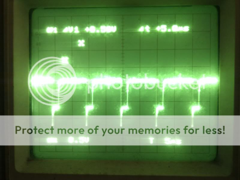
So i was looking at the wave forms on fets q213 214 209 210 and noticed that q207/q210 weren't as square as the rest of em as you can see here:
Q213/Q212

Q214/Q211
Q208/Q209
Q207/Q210

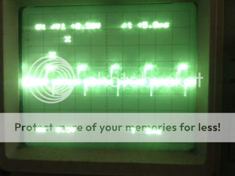
Come to find out R235 that is a 100ohm resistor was open. So replaced it and now Q207/Q210 show this wave form:
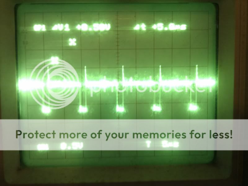
think that may have contributed to the blowing of the outputs this time around?
Q213/Q212
Q214/Q211
Q208/Q209
Q207/Q210
Come to find out R235 that is a 100ohm resistor was open. So replaced it and now Q207/Q210 show this wave form:
think that may have contributed to the blowing of the outputs this time around?
Alright so I just placed an order for
-24 FQA28N15 mosfet's (have lots of extras, also the input capacitance is much lower on this fet than the original and most specs are very very similar).
-2 4.7uf filtering caps (iu case one breaks)
-3 IRFZ48V for a different amp...
Hopefully i can get this rf amp working or blow up $20 worth of fets trying lol
- Status
- This old topic is closed. If you want to reopen this topic, contact a moderator using the "Report Post" button.
- Home
- General Interest
- Car Audio
- Rockford T10001BD blown output fet