I just got this amp in tonight for repair.oes anyone have a schematic for this or know the order the outputs go in it? Someone worked on it before and have power supply fets in the output section. Also the fets that are in this amp now are irf1010e's not sure if they are original or not.
And in the output section they have 540's 9540's irf9z34's and irf1010e's and i know thats not correct at all correct me if im wrong. But a 9540 and a 1010e working together?
Any help would greatly be appericated
And in the output section they have 540's 9540's irf9z34's and irf1010e's and i know thats not correct at all correct me if im wrong. But a 9540 and a 1010e working together?
Any help would greatly be appericated
Yeah they have that in the bass channel sort of like a staggered output stage. RF has the schematic posted on their web site last I looked. It threw me the first time i saw it also. Plus if this is the defective channel be prepared to tweezers out some of the SMD transistor components sitting behind the outputs. I have never seen one of the just blow the outputs only, they always take down the drivers stages and several resistors also along the way....Have fun....
Thanks 1moreamp,
Yeah it took out the 2a's the emitter resistors, the 10 ohm surface mount resistors, all the power supply fets, the gray and black diode , one of the 1n4003 diodes. Some of the 540's and 9540's in a couple channels.
Thats what i found so far wrong with it in 25 mins could be more then that.
But the guy is willing to pay for it i told him it would probably be an expensive repair
the sub channel has IRF9Z34,IRF5210,IRF540, and IRF1010E .
The other channels are 540's and 9540's .
Which the sub channel and 2 of the other channels have shorted outputs.
The power supply is using IRF1010E's Is this a good fet to use or should i switch to something else since this guy likes to abuse his equiment
The other channels are 540's and 9540's .
Which the sub channel and 2 of the other channels have shorted outputs.
The power supply is using IRF1010E's Is this a good fet to use or should i switch to something else since this guy likes to abuse his equiment
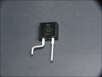
That's a BYV28-150 and is difficult to match (for durability) with anything of a comparable size. If you're not going to use an exact replacement, I'd suggest using something like an MUR820 bent similar to the one in the following image. The left leg in the photo would be the same as the striped end of the original diode. If you use this as a replacement and the tab has to be cut off (for clearance), do so before you install it.
Attachments
Ok i took the outputs out of the amp.
I replaced the bad fet.
When i hook power and ground to the amp im fine if i apply the remote lead it draws excessive current.
Then i test the fets they read shorted for like 10 sec's then i test them again and they all test fine in and out of the board. gate resistors check fine and the drivers appear to be fine
Wondering what else i should check?
- Status
- This old topic is closed. If you want to reopen this topic, contact a moderator using the "Report Post" button.
- Home
- General Interest
- Car Audio
- Rockford Fosgate 600.5