Inductor out and NO connections to the amp but the following:
Connect the B+ from your power supply to one end of the resistors. Connect the other end of the resistors to the positive speaker terminal (yes, speaker terminal). Connect the ground from your power supply to the negative speaker terminal.
What gets hot on the board?
Connect the B+ from your power supply to one end of the resistors. Connect the other end of the resistors to the positive speaker terminal (yes, speaker terminal). Connect the ground from your power supply to the negative speaker terminal.
What gets hot on the board?
I'm hacking away but I am about to the point where I will have to remove the entire top copper plate that one side of the capacitors mounted to. Will this cause problems with conductivity. This being a multilayer board, do you think it will be difficult to to make connections to anything that is connected to this plate? also this plate is pretty wide, by removing large sections of it can't it cause current handling issues for the remaining pieces of the conductor?
The amp may not be repairable. To make it repairable, you MUST get rid of any fiberglass that could conduct between adjacent copper traces. If this is a 2-layer board (only top and bottom), it should be repairable. If it's a 3 or 4 layer board, it may not be repairable until Rockford releases the schematic diagram. Even then, it may not be practical to repair.
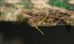
If you find copper traces embedded in the fiberglass (not top of bottom traces), this board has more than 2 copper layers and you will likely have to wait until the schematic diagram is released to repair it.
The attached image shows a board with an internal copper layer.
If you find copper traces embedded in the fiberglass (not top of bottom traces), this board has more than 2 copper layers and you will likely have to wait until the schematic diagram is released to repair it.
The attached image shows a board with an internal copper layer.
Attachments
- Status
- This old topic is closed. If you want to reopen this topic, contact a moderator using the "Report Post" button.
- Home
- General Interest
- Car Audio
- Rockford 1500-1bd